Project Description
LANDMARK TRAVEL CENTER STANDFIELD, OREGON ON INTERSTATE 84 AT EXIT 188
New Pump Station and 1,200 GPM Well to fill 1,000,000 gallon Reservoir together with a new 16” water line connecting to the town of Stanfield, The all new Electrical and Control System Design included:
- Motor Control Center (MCC) housing 200 HP Variable Frequency Drive (VFD) deep well pump.
- Automated pump Control System using Programmable Logic Controller (PLC).
- On site Operator control and monitoring station with Touch Screen Graphical Interface.
- Telemetry connection to city Supervisory Control And Data Acquisition System (SCADA).
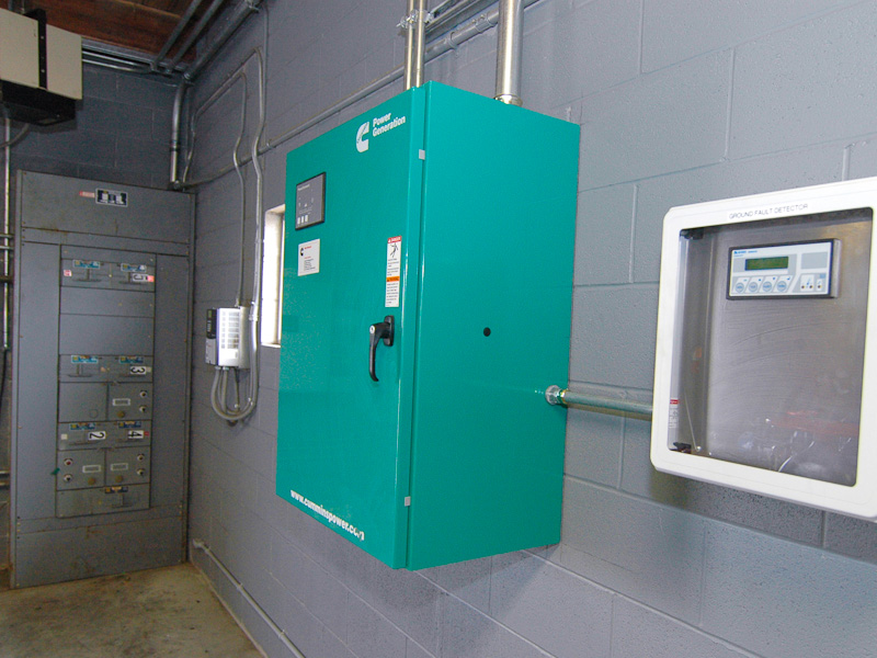
- Energy Efficient Lighting Design; Backup Generator at this site and North Pump Station.


WEED PATCH or CONSTRUCTION SITE
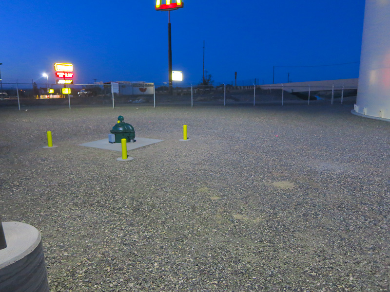
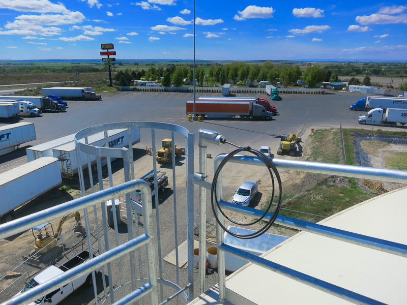
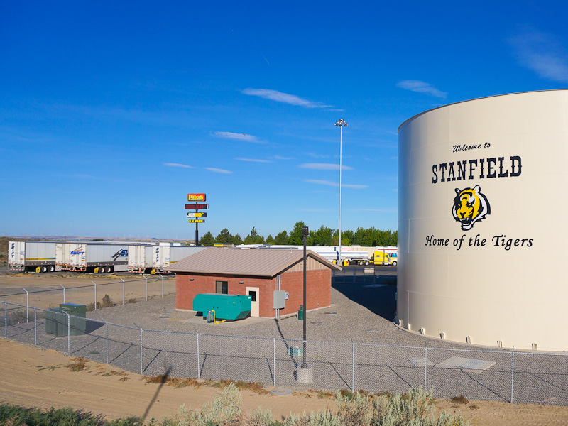
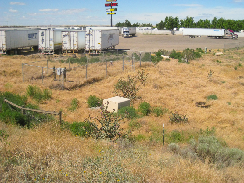
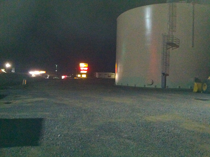
The town is about a mile North of the site (picture above and left) and at a lower elevation (~100’) which has always necessitated a separate well for the travel center. The well is visible inside the fence and in the larger picture at the top of the page just right of the generator. In the new design it became another source of water for the reservoir with the travel center water needs now served by the new pump station.
With the 16” water line connection to the city, the new reservoir and pump station operate together with the smaller existing pump station located about half a mile North of town. The Electrical Design also included the addition of a standby generator at the North Pump Station.
DESIGN & CONSTRUCTION IN TWO PHASES
Project planning began in 2010 and by the middle of 2011 the first construction phase was beginning to take shape. The first phase of the work under separate contract from the Pump Station included:
-Drill and test pump the new deep well at the site.
-Build the new 1,000,000 gallon reservoir and associated piping.
-Construct the new 16” water line from the site to town.
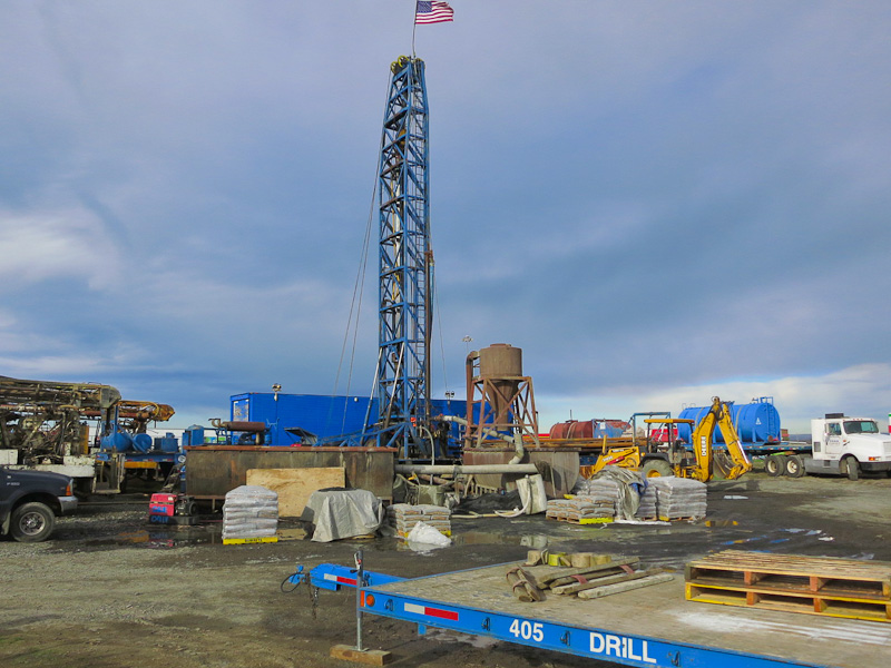
In this picture from December 2012 looking North at the site you can see the drilling rig working over the well location.
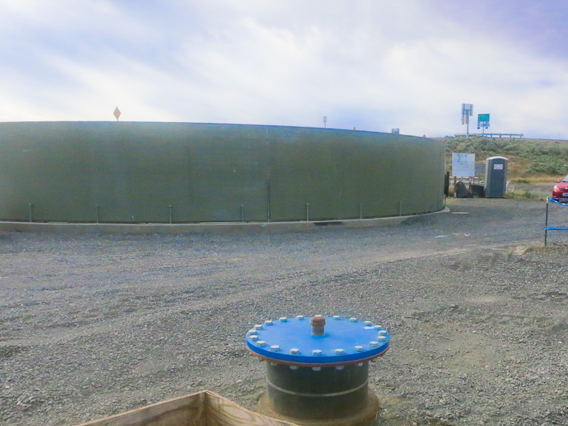
May 2013 looking South toward the freeway interchange the completed 20” diameter well casing is visible in the foreground. The new reservoir is beginning to take shape with the first row of welded steel panels in place.
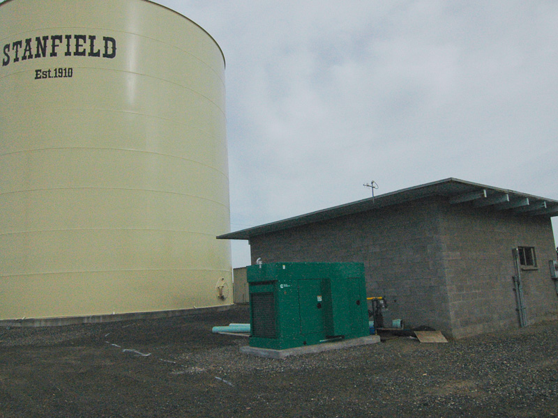
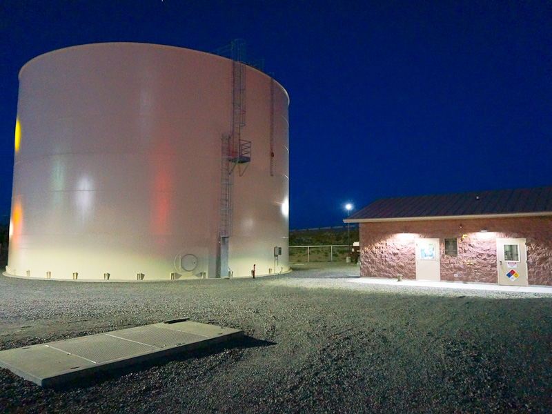
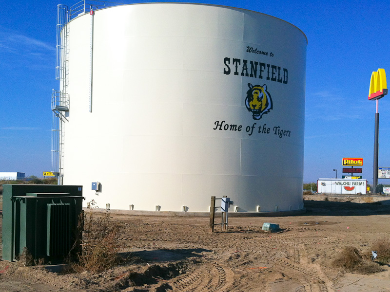 October 2013 looking North at the site. The new reservoir is now complete including the town logo. It is connected with the town water system and ready to go on line.
The control structure for the small well serving the travel center is visible in the foreground and will continue to operate until the new pump station is on line.
The pad mounted transformer to the left is new and located to the South of the original transformer (first photo). It is also larger to accommodate the pump station that is scheduled to be built next.
 ELECTRICAL DESIGN OVERVIEW
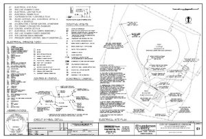
Click on the Drawing to view Sheet E1.
The Electrical Site Plan provides an overview of the site layout and underground connections. It indicates the old and new original transformer locations. Both wells connect to the new Pump Station eliminating the control structure seen in the last picture above.
 ELECTRICAL CONSTRUCTION
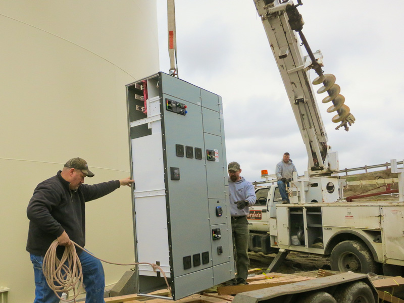
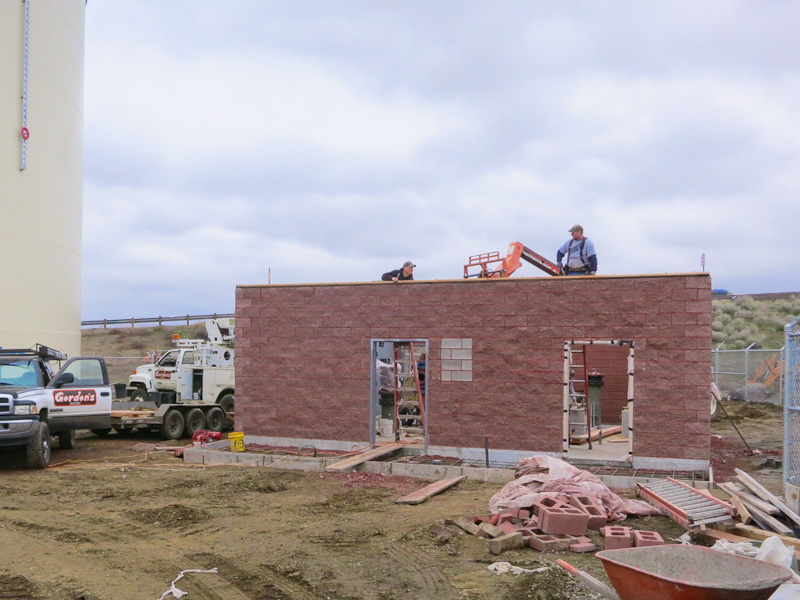
February 2014 placing items in the structure that would otherwise be difficult to get through the doors.
There’s a lot of work that’s been covered up in this photo such as a maze of underground piping and electrical conduits. The building floor slab is complete, walls are up and the roof will be on in a matter of days.
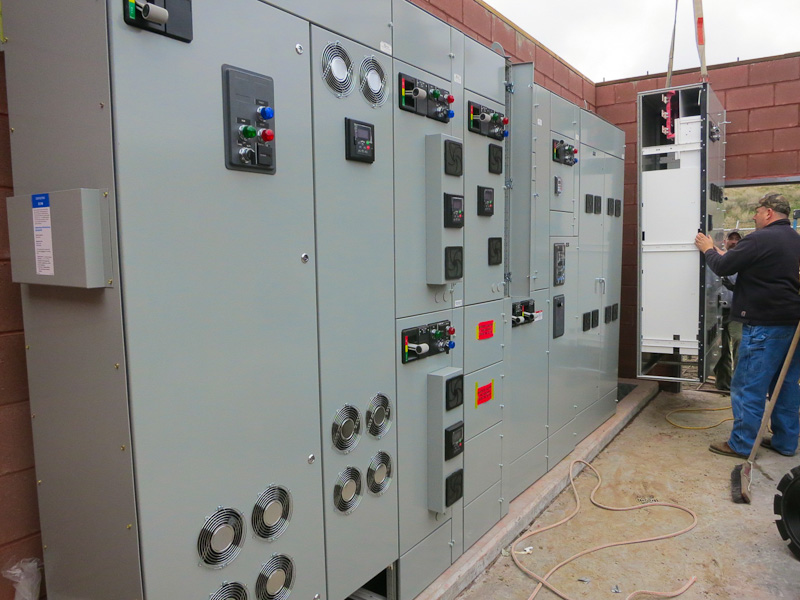
The Motor Control Center (MCC) is lifted over the wall one section at a time and fastened together. It sits on a raised curb. Most conduit connections come and go through the open channel in the concrete at the bottom.
The benefit of the MCC is that it consolidates power and other components into a clean organized enclosure. Additionally the MCC saves space and labor. Designed and specified with the electrical design the MCC can be put out to bid like any other component.
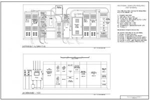 Click on the Drawing to see the MCC Story
The drawing presents two ways of doing the same thing. First, individual components such as VFD, Automatic Transfer Switch, Soft Start, Service Disconnect, etc. are wall mounted and connected using conduits to build the system. It barely fits the available space requiring days of field assembly.
Second is the MCC configuration – as designed. Same components with connections prewired internally. See additional pictures.
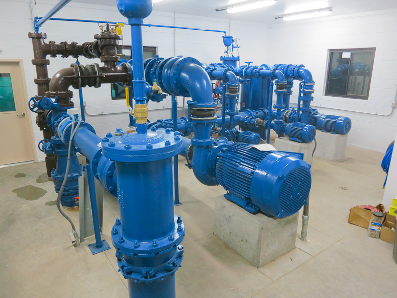
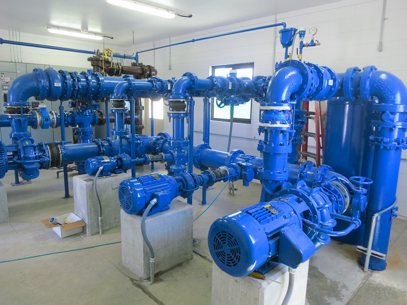
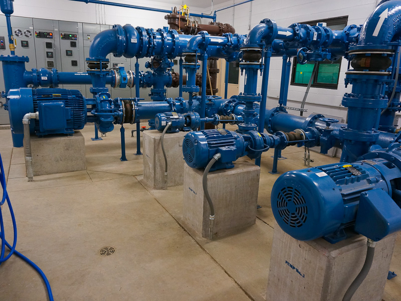 MOTORS & MOTOR CONTROL
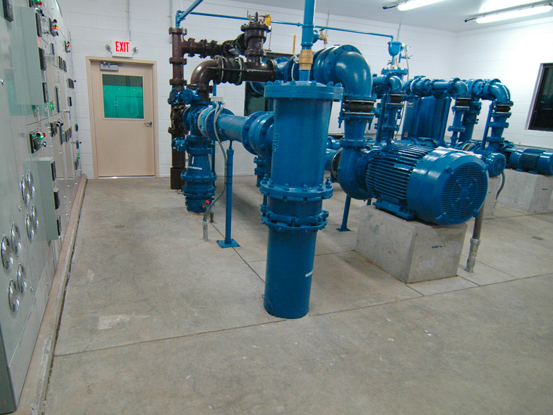
To be energy efficient and reliable three phase motors must be carefully selected and their operational life should be monitored to minimize unexpected failures. This includes environment, voltage imbalance, voltage level, VFD harmonics and vibration.
The electrical design includes provisions within the MCC and control system to identify undesirable operating conditions and take appropriate action and/or notify the operator.
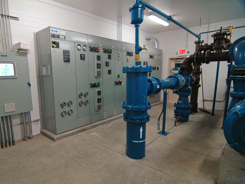
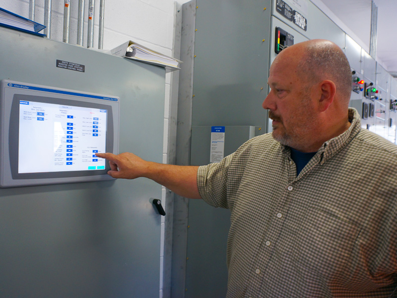
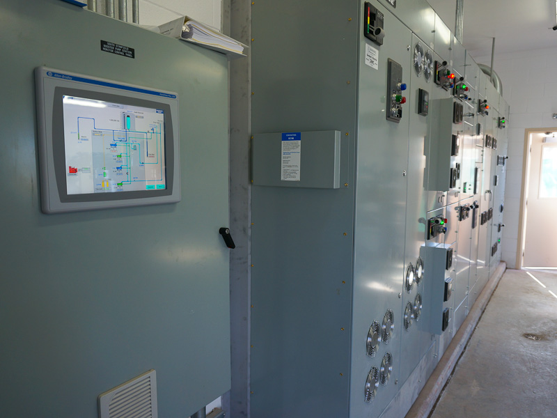
 Space saved by the integrated MCC Design allowed for close proximity of physical and virtual controls. Each motor is controlled by a 3 position Hand Off Auto (HOA) switch on the MCC. The virtual HOA is on the touch screen which is the Human Machine Interface (HMI).
In a system such as this the operator should have manual fall back operation independent of automated control. Each HOA on the MCC provides this – another benefit of the MCC.
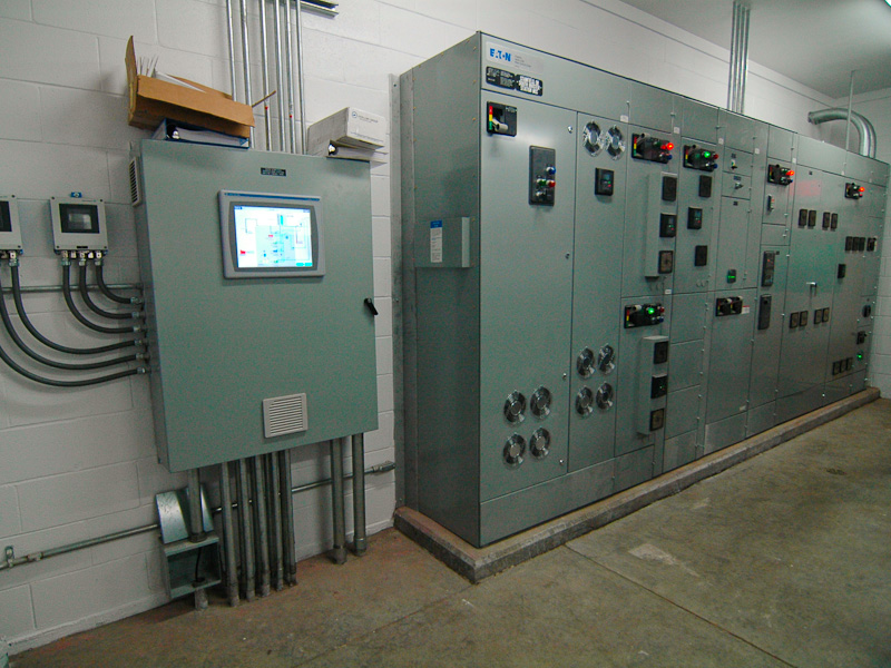
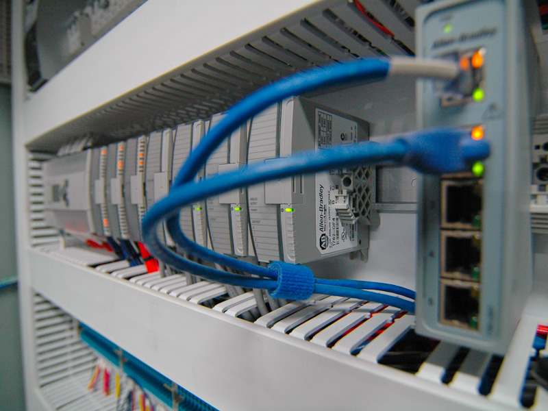
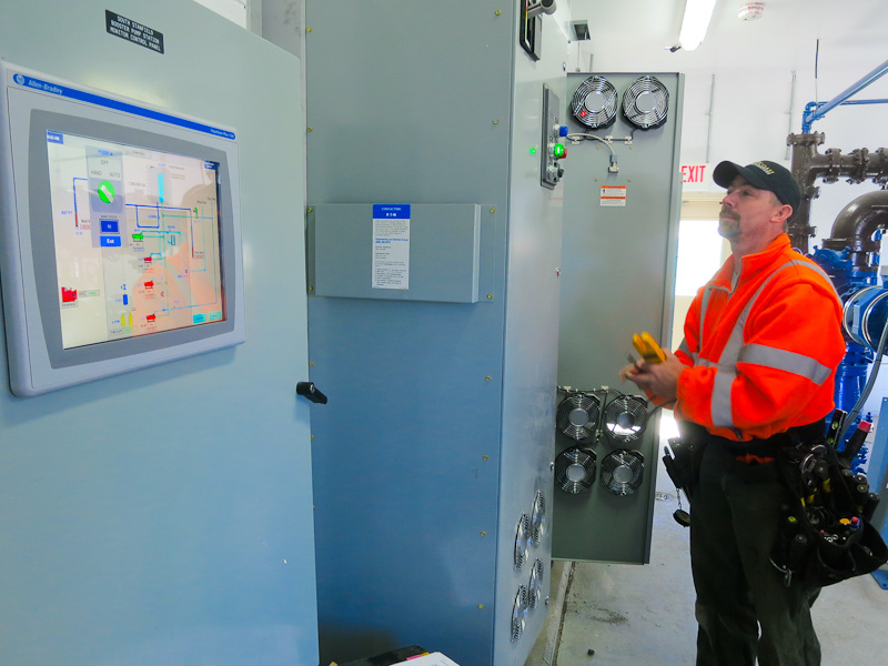
The control system next to the MCC provides automated operation of the pump station. Instrumentation values such as flow rates, flow totals, pressures and levels provide the PLC with inputs for programmed responses to control water storage and flow.
Under normal conditions the operator monitors the system at the touch screen HMI while at the station. A radio telemetry link to the city office permits remote monitoring. This remote computer terminal can be accessed through a secure encrypted internet connection to monitor the system virtually anywhere. See SCADA below.
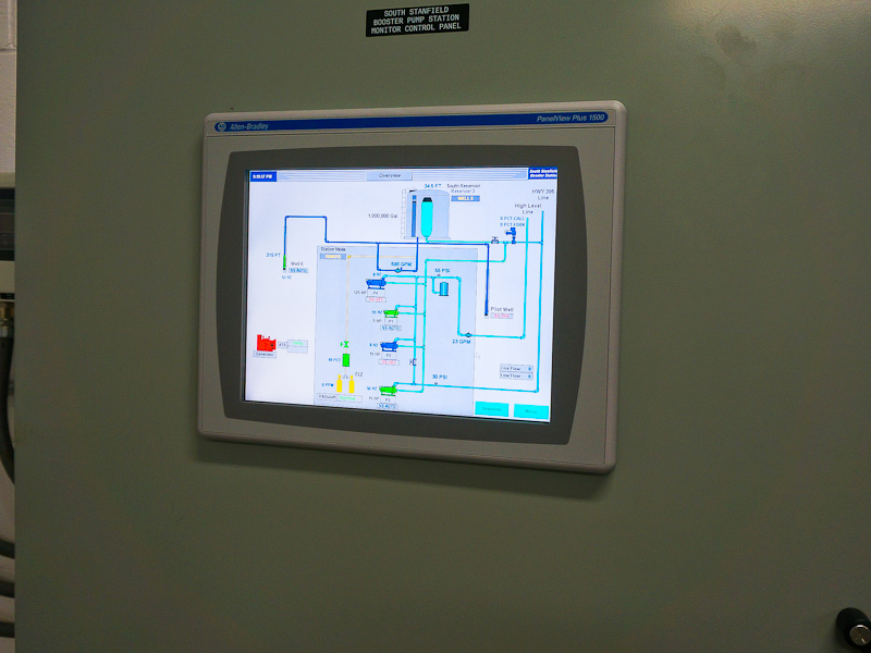 A benefit of the touch screen is the ability to graphically represent the water system. The resulting picture conveys system status at a glance. But there’s more. Touch a component on the screen and a detailed view opens for that item enabling further interaction such as setting input, manual operation, history and status.
On other screens, data including recorded flow or pressure can be displayed on a graph for a recent time period (i.e. trend screen). Other options include help screens, alarm display and animation using color. In the screen picture the aqua color indicates the reservoir water level – in addition to the numerical value.
AUTOMATED CONTROL OF STANFIELD WATER SYSTEM
- Graphical view of the city water system displayed on SCADA Computer at the city office. The new South Pump Station and Reservoir (left); North Pump Station and Reservoir on the right side.
- SCADA provides an interactive picture of the system process. Components are represented on this screen with status indicated by color. Selection of an item (i.e. a pump) will bring up another screen having additional information relevant to the selected component. Additional screens are provided for the operator to enter settings, check alarms, control the system manually or to display recorded data.
- SCADA records operating parameters such as flows, totals and pressures providing operational history to help the operator manage the system and to satisfy regulatory reporting requirements.
- This functionality at the city office results from the radio telemetry link to the pump stations. Similar capability can be extended using a secure internet connection to a laptop computer or mobile device (smart phone).
 SITE & INTERIOR LIGHTING DESIGN
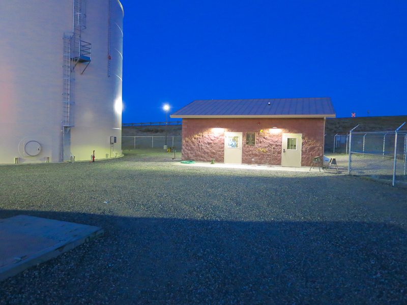
At left of the larger picture (top of page) notice the high mast lighting pole in the adjacent truck lot. Light in this picture (October 2013) is coming from this pole. It would be “light trespass” in the big city but, not in this case!
This light from the adjacent truck lot was mapped using a light meter and resulted in a reduction of poles and fixtures necessary to adequately light the site. See next and Gallery pictures for the result.
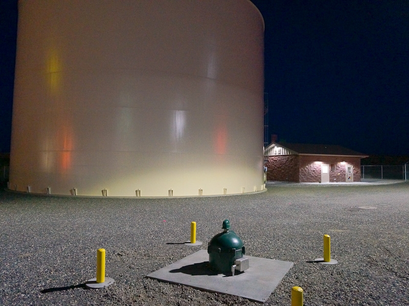 Only one pole with an area light was necessary for general site lighting of the pump station after mapping the light from the adjacent lot. Exterior site lighting was designed using energy efficient LED fixtures. These included the single area light, flood light fixture to illuminate the “Home of the Tigers” logo and the five wall mounted fixtures around the outside of pump station building.
T8 fluorescent lamps, electronic ballasts in an enclosed gasketed fixture with a polycarbonate lens were used for interior lighting of the pump station. Maximum ambient operating temperature for comparable LED fixtures was not suitable for the application.