Project Description
Electrical Design Project – Water System Improvements
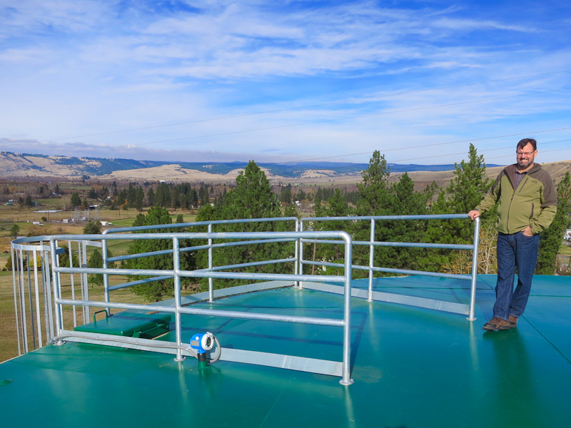
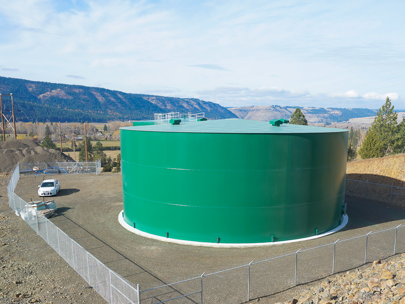
Reservoir Site at Project completion, November 2014. Existing reservoir refurbished (foreground); and the new larger second reservoir. The new reservoir was designed with matching base elevation and height so that the pair could operate together under normal conditions. For years a single deep well has served as the town’s water source. Water is pumped up to this reservoir site on a nearby hill. Distribution is by gravity flow from the reservoir to a pressure regulating vault and then on to the town’s water system patrons.


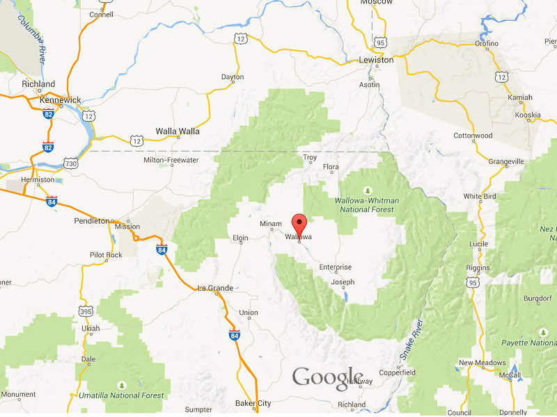 WHERE IS WALLOWA, OREGON
Click on the map to view the surrounding area.
Wallowa is a beautiful little town about 45 miles East of La Grande on Highway 82 in the Northeast corner of Oregon. Surrounded by the Wallowa Mountain Range the area is often referred to as the Oregon Alps. It is home to The Eagle Cap Wilderness Area – Oregon’s largest.
 EXISTING WATER SYSTEM
The water system consisted of a single well pump station controlling a submersible pump transferring water to a 270,000 gallon storage reservoir about a quarter mile away at an elevation 170’ higher (picture above). This was all good except for the single water source and the need for more storage to meet demand and required fire flows.
Difficulties with the system included a single water line to the reservoir – undersize to provide additional flow and it had ruptured on at least one prior occasion.
 Water level at the reservoir was transmitted to the pump station through a 24 VDC cable buried next to the water line. This had become problematic due to water intrusion from numerous splices.
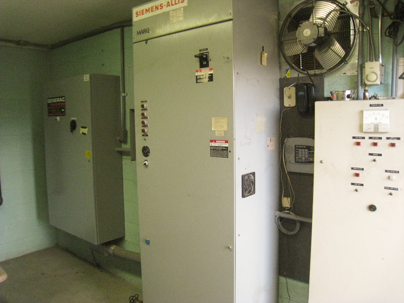
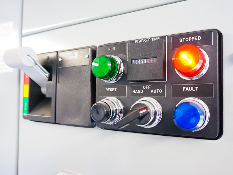
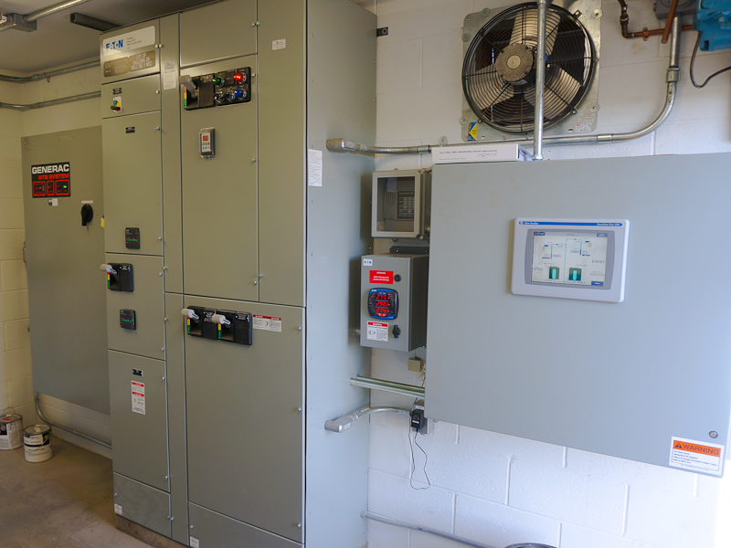
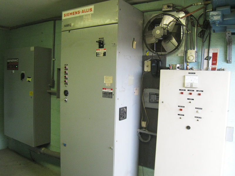
Picture (left) is inside the pump station. The well pump was operated by an older soft start (center) controlled by the smaller panel (right) based on reservoir level. At times the circuit breaker would trip for unknown reasons leaving the well out of service. A diesel generator and Automatic Transfer Switch (ATS) to the left had been installed to provide a backup power source.
 NEW WATER SYSTEM & ELECTRICAL DESIGN
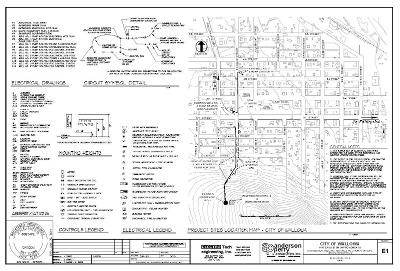
Click on the Drawing Sheet E1. The design included:
-Upgrade of existing Pump Station, Reservoir and 12” water line.
-A new Automated Touch Screen Operator Control System.
-New 16” water line reservoir site to the city distribution system.
-New Well 2 and Pump Station added North of existing Well 1.
-New 500,000 gallon Reservoir 2 and Reservoir Instrumentation.
WELL No. 1 PUMP STATION IMPROVEMENTS
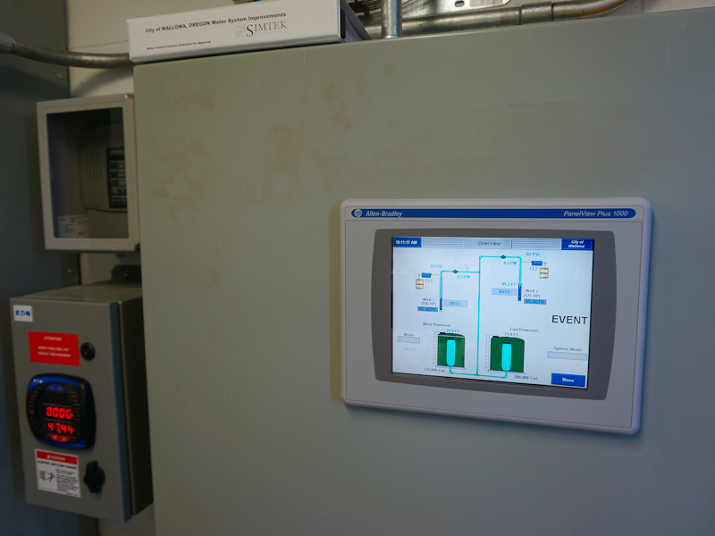
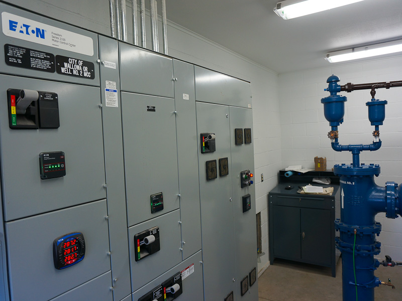
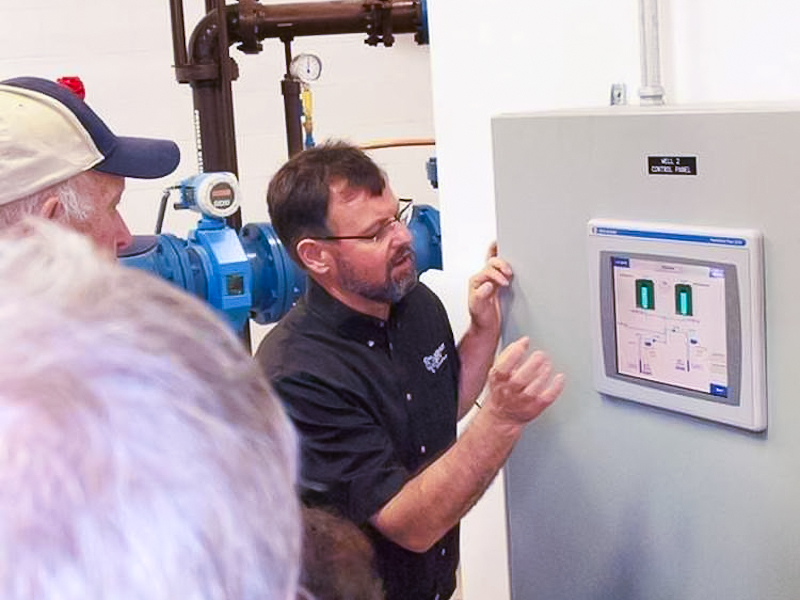
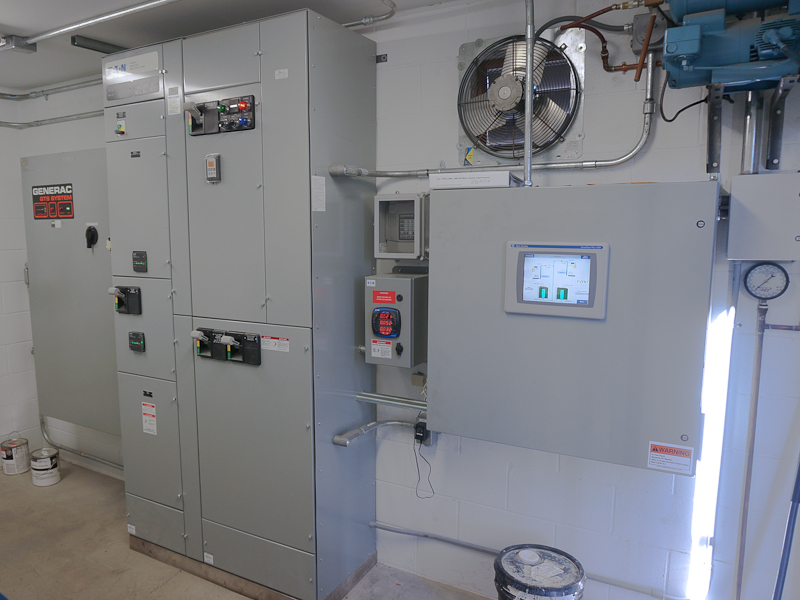
Well 1 Pump Station was gutted and rewired. Before picture (above); after pictures (left) tell the story. New Motor Control Center (MCC) with new Automated Control System and Operator Touch Screen (right). Next picture (opposite wall from MCC) is the new Magnetic Flow Meter and Pressure Instrumentation. Upgrades to the Pump Station included:
 >Plastic conduits replaced with Galvanized Rigid Steel (GRS)
>Older Well Soft Start replace with new Solid State unit in MCC
>Electrical surge protection added in new MCC
>Power and voltage monitoring added with new MCC
>New telephone dialer for operator remote notification
>New radio telemetry communications to reservoir site
>Programmable Logic Controller (PLC) automated system
>Operator touch screen control and monitoring system
>System status (flows, pressures, levels, etc.) displayed
>System Operating history recorded and displayed on screen
>New magnetic flow meter records water flow to reservoir
>New pressure instrument provides reservoir level sensing
>New energy efficient lighting inside and outside Pump Station
 To minimize single points of system failure the Design included selective redundancy- including:
>Backup operation using pressure should instrumentation fail
>Operation on generator should utility power fail
>Backup operation on either pump station should one fail
>Operation using either reservoir individually or both together
New more energy efficient lighting was specified such as these LED fixtures at Well 1 Pump Station.
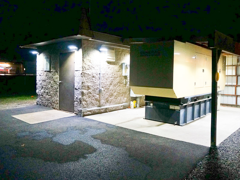
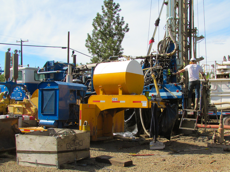
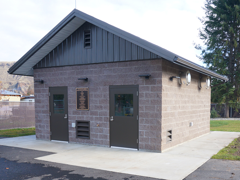 NEW WELL No. & 2 PUMP STATION
Well 2 connects hydraulically to Well 1 and to the existing 12” line to fill the reservoirs. Two blocks North of Well 1 a vacant lot became the location for Well 2. The site even had a 3-phase distribution line across the street.
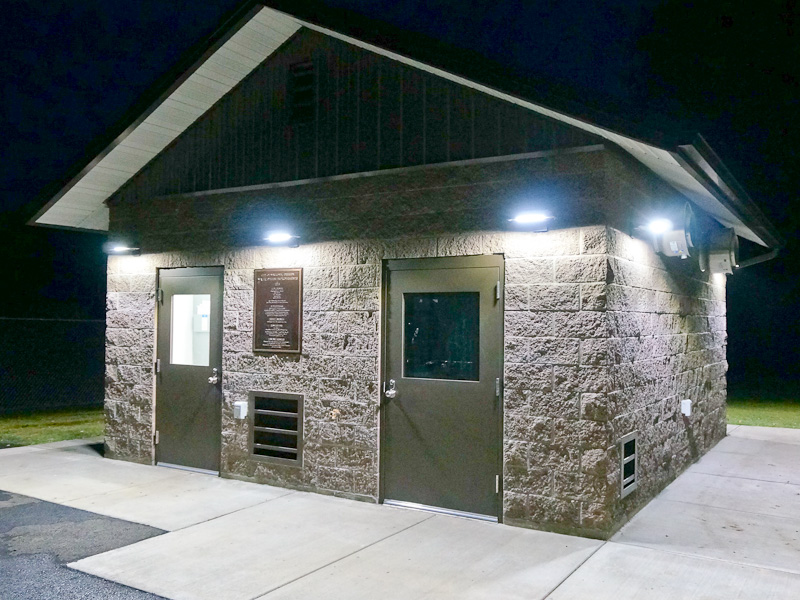
See picture of new Well 2 Pump Station. Two doors open to separate areas. Control room (left); chlorination room (right).
The Electrical Design had to coordinate operation of the two wells. Under normal conditions the stations alternate duty on a schedule set by the operator but, the two wells can operate together. A Variable Frequency Drive (VFD) was required at Well 2 to control the combined withdrawal rate limited by the city’s water right. For this and other reasons the design included a high speed Ethernet Telemetry link between the two sites providing the following benefits:
-Operator touch screen can display or control either station
-Should one station fail it can automatically call the other
-Provides redundancy of stored data by having it in two places
-System defaults to Well 1 with the generator on power outage
-Facilitates station alternation and simultaneous operation
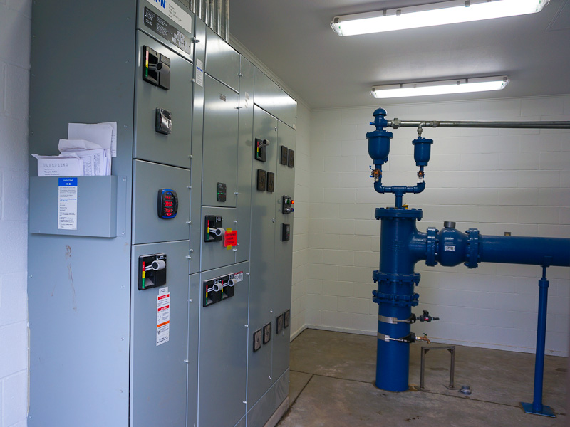
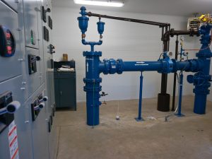
The MCC at Well 2 visible in the picture (left) consolidates power components such as the service, distribution panel and well pump VFD which would otherwise take up more space and labor to install.
Water comes up from the 125 HP submersible well pump in the vertical pipe to the right of the MCC. It then travels horizontally through the instrumentation and down and on to the reservoir.
 The MCC at Well 2 visible in the picture (left) consolidates power components such as the service, distribution panel and well pump VFD which would otherwise take up more space and labor to install.
Water comes up from the 125 HP submersible well pump in the vertical pipe to the right of the MCC. It then travels horizontally through the instrumentation and down and on to the reservoir.
 INDUSTRIAL AUTOMATION
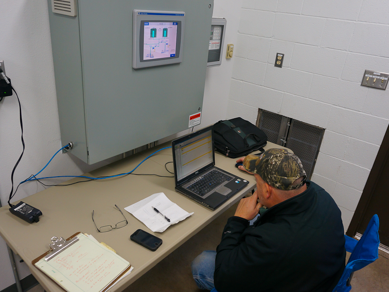
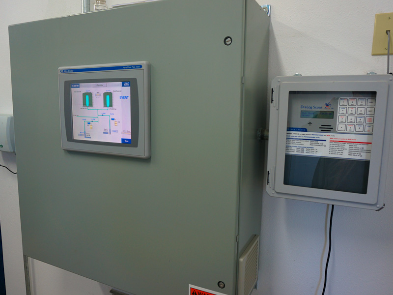
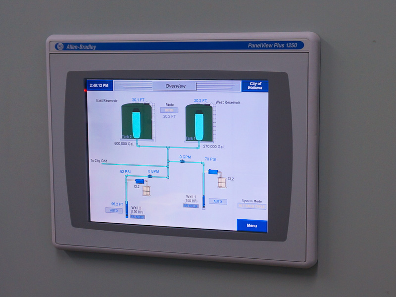
See next two photographs. One of the benefits of the touch screen is the ability to graphically represent the water system being controlled. The resulting picture conveys system status at a glance. But there’s more. Touch a component on the screen and a detailed view opens for the selected item enabling further interactions such as setting input, manual operation, history and status.
 On other screens, data such as recorded flow or pressure can be displayed on a graph for a recent time period (trend screen)or alternately in list format. Other options include instruction and help screens, display of alarms and animation using color. In the screen picture the aqua color indicates the reservoir water level in addition to the numerical value.
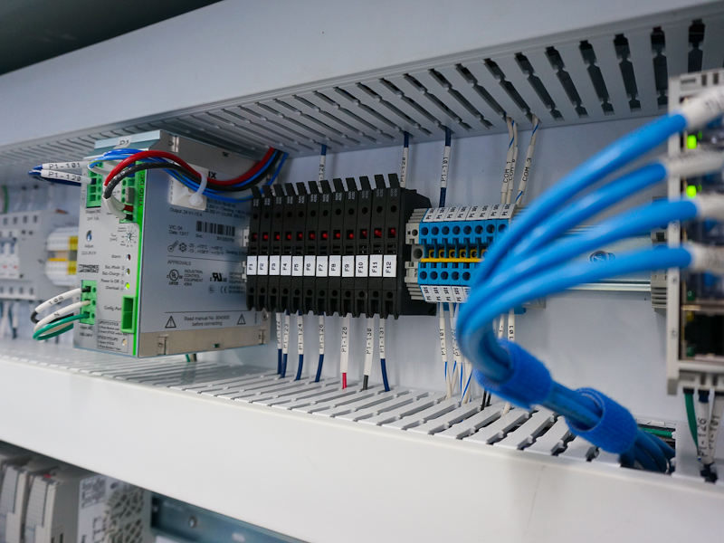
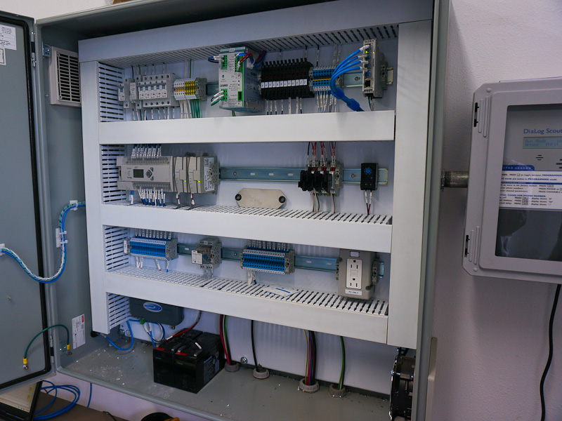
Look inside the cabinet in the next picture. Industrial control hardware is built to a higher standard than more familiar consumer grade products and thus is more rugged and reliable. Consumer grade hardware is typically not used in applications such municipal services or where life safety could be an issue.
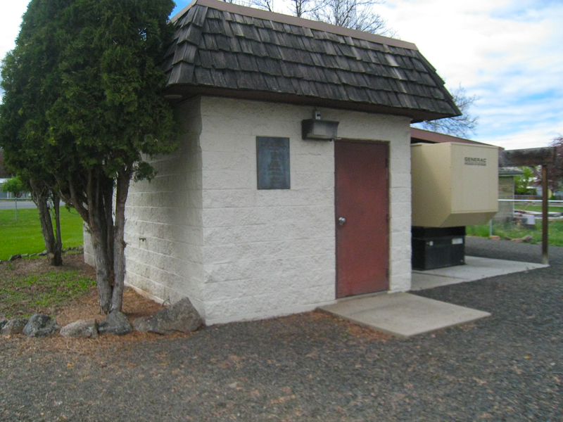
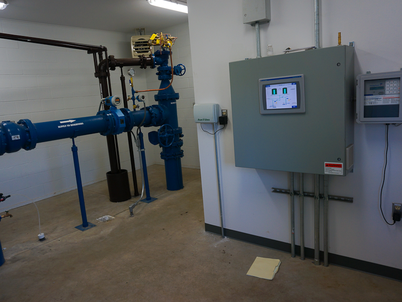
 RESERVOIR SITE INSTRUMENTATION
There was no power at the reservoir site in original system which relied on a buried cable to monitor reservoir water level and thus control the pump at Well 1. This became problematic due to a pipe break and/or digging that cut the cable. Water intrusion from subsequent splices further degraded the cable to the point that it was barely useable.
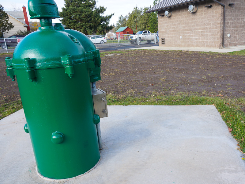
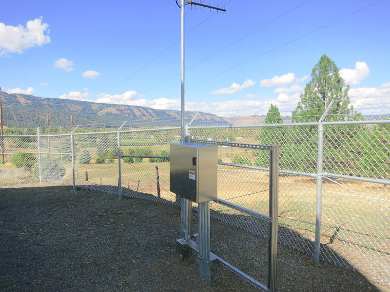
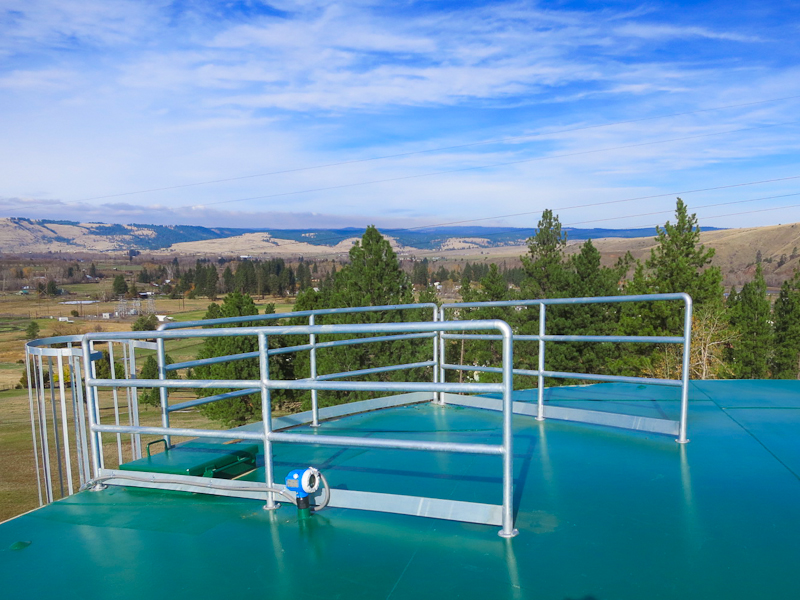 To resolve this issue the Electrical Design included an underground power line to the reservoir site to operate instrumentation and radio telemetry necessary to monitor reservoir levels. The system operates using an ultrasonic level detector in each reservoir to read the water level which is then transmitted to the well stations over the radio link (pictures).
Because the water system relies heavily on reservoir levels for its operation the Electrical Design also included a fall back method of operation should the radio system or instrumentation fail. In this event, the line pressure sensor at each pump station has sufficient accuracy to read the reservoir level and to continue operation.