Project Description
Wastewater Treatment Plant Upgrades
- New Operations Building (right). Existing Generator Building (foreground).
- Existing Labe building center, Spiragester (background), Clarifier (left).
- Design included extensive reuse of existing structures with new site lighting.


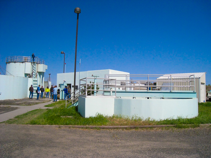
THE PROBLEM
The City of Stanfield, OR operated an aging mechanical treatment plant that no longer met current DEQ standards. A number of areas had to be addressed in the design to bring the plant into compliance including a new primary clarifier, sludge pumps, air pumps to improve spiragester operation, modifications of the two secondary clarifiers and chlorination improvements.
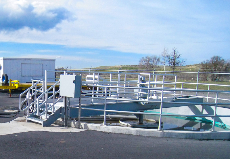
The picture illustrates some of the existing plant at the May 6, 2008 pre-bid conference. One of the secondary clarifiers is in the foreground; lab building is visible behind (center) and the spiragester a two story combination sedimentation and sludge digestion unit left.
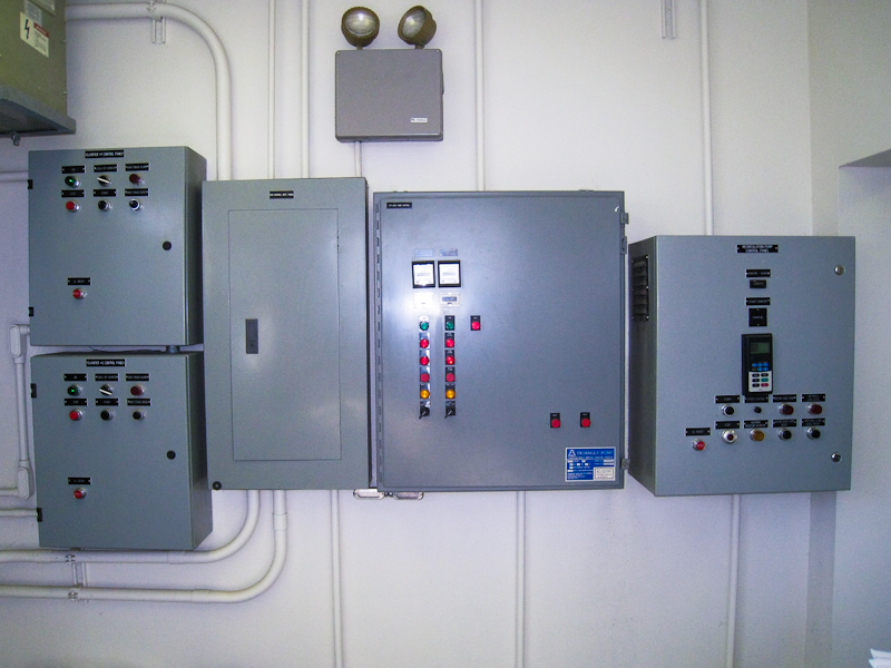
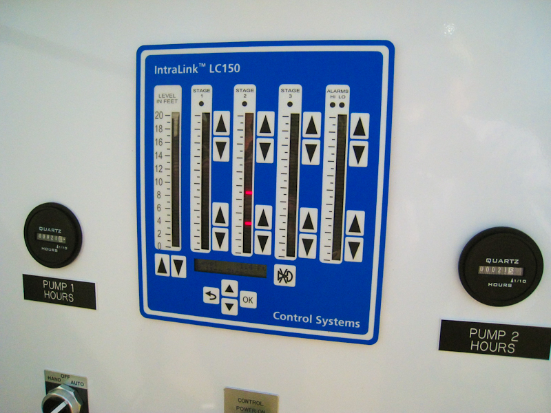
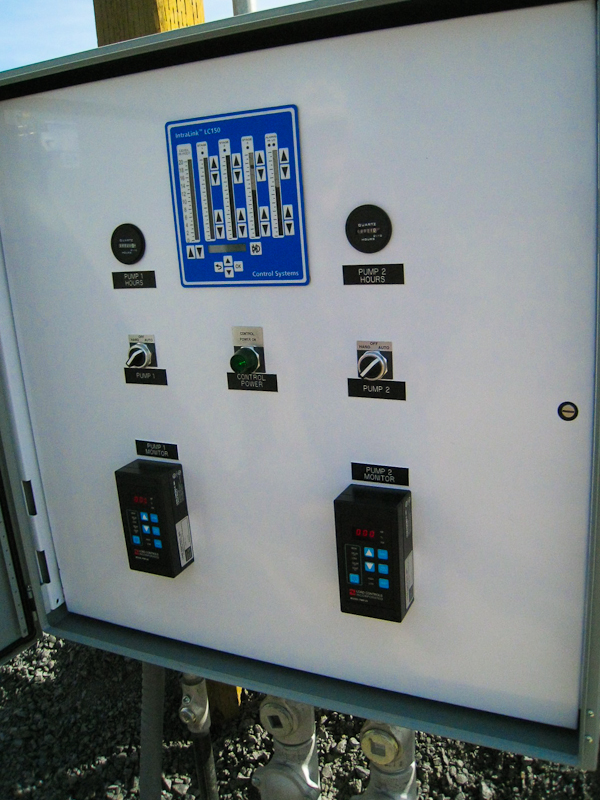
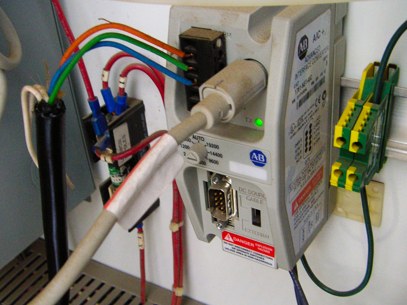
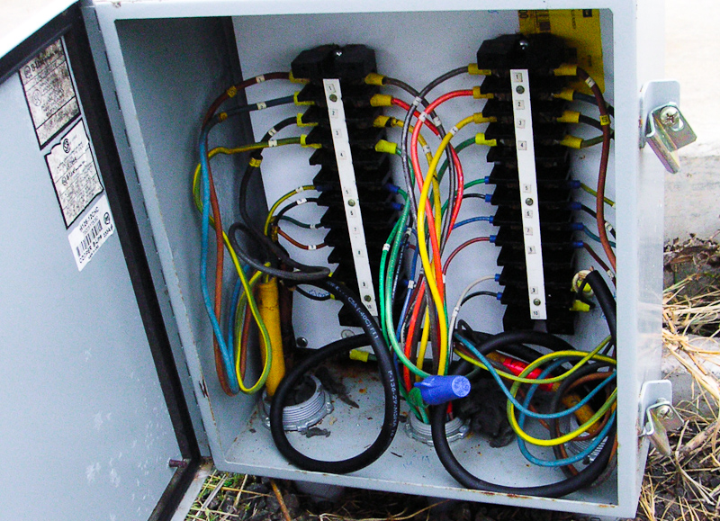
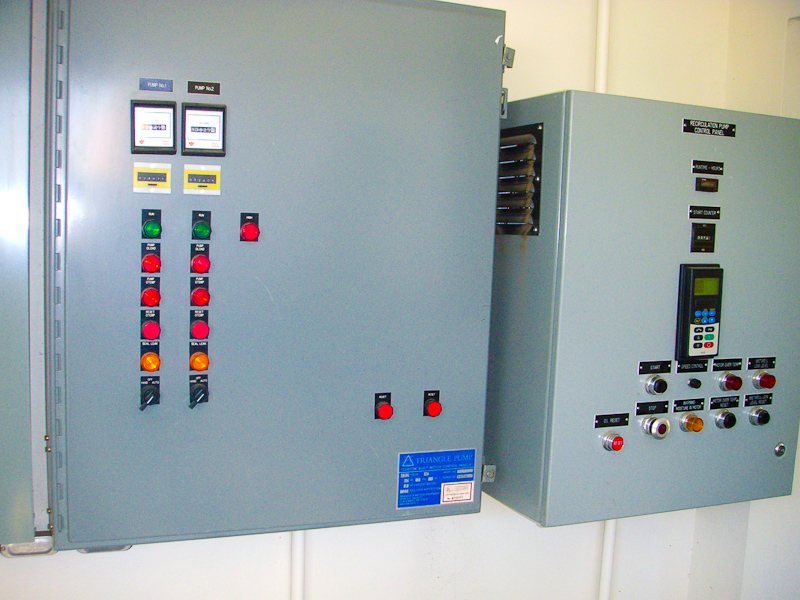
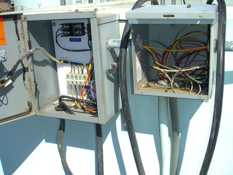
Typical of the existing controls at the plant: individual panels for each of the dozen or so major components in various locations. An early electrical design objective was to consolidate these controls.
In addition to DEQ concerns, control and monitoring of plant needed to be streamlined – ideally to a central point. Design of the control system included a new PLC and touch screen panel for operator control. The design also included a SCADA system to collect operating history and tie in outlying systems such as lift stations.

ELECTRICAL & CONTROL SYSTEM DESIGN
Sheet E5 of the 15 sheet Electrical and Controls Design details the conduit layout of the 2± acre site including the new mechanical building (center). It became the new focal point of control and power distribution for the project. The Drawing indicated the location of the new primary clarifier above up and to the left; with provisions for a second when needed (left).
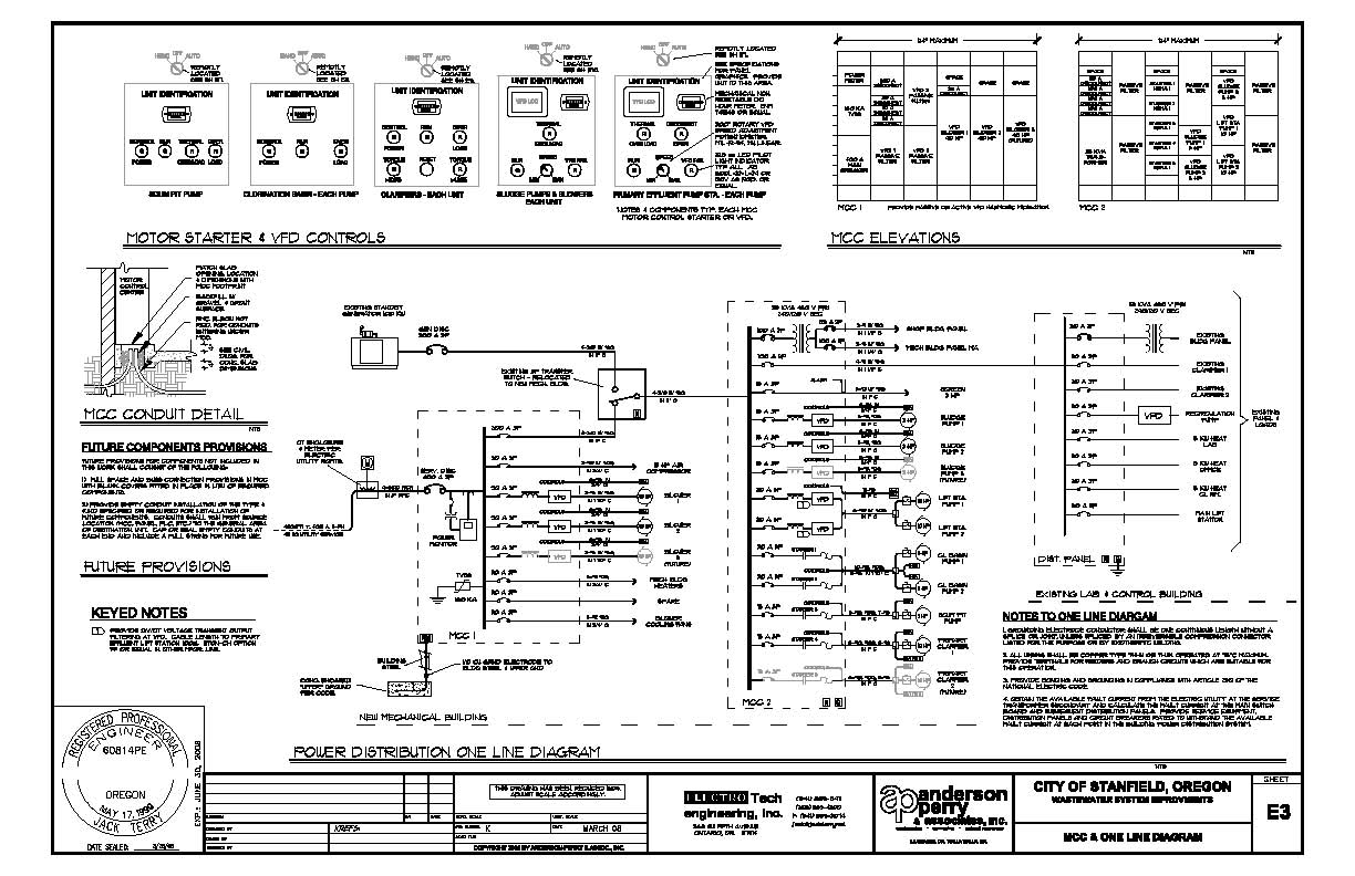 SHEET E3: ELECTRICAL ONE LINE DIAGRAM FOR THE PROJECT.
A two Motor Control Center (MCC) design was selected in order to consolidate control functions and minimize space requirements. The plant had an existing standby generator and Automatic Transfer Switch (ATS) but it didn’t have capacity to carry the full load. We were able to save the cost of replacing it by separating sources for the two MCCs. MCC1 became utility power with nonessential loads (left in the Drawing) while MCC2 (right) carried the loads essential to keeping the plant on line including the lab building.

RESULTS
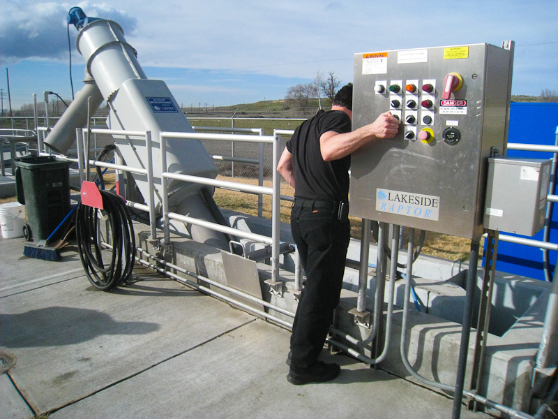
One of the design objectives was to include a screen to filter out inorganic debris from the wastewater flowing into the plant. New mechanical screening channel and influent sampler (blue) can be seen here – the new primary clarifier just out of the picture to the left.
The next series of pictures were taken in March of 2011, about two years after completion.
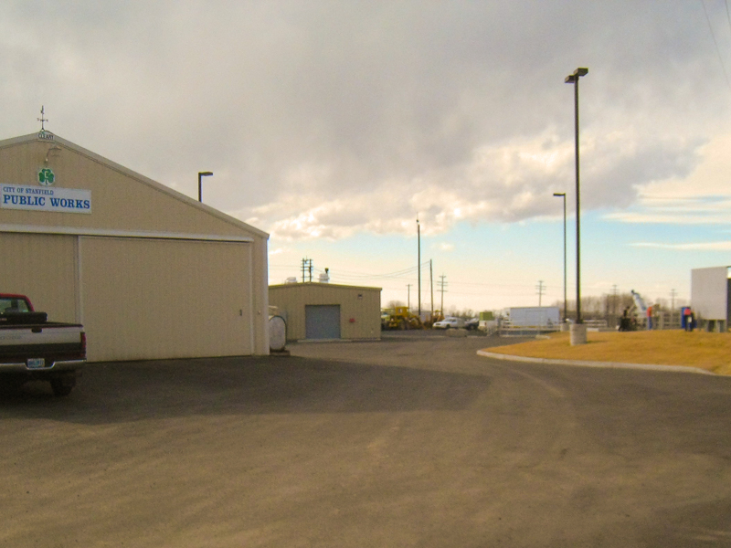
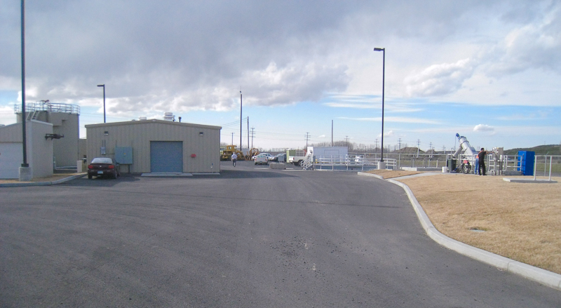 The New Mechanical Building with the new main utility electrical service enclosure visible (center left). The Spiragester which provides primary settlement is visible just to the left of the Mechanical Building. The existing lab building and standby generator building can be seen at the left edge of the picture. New curb, driveway and site lighting finished off sit clean-up.

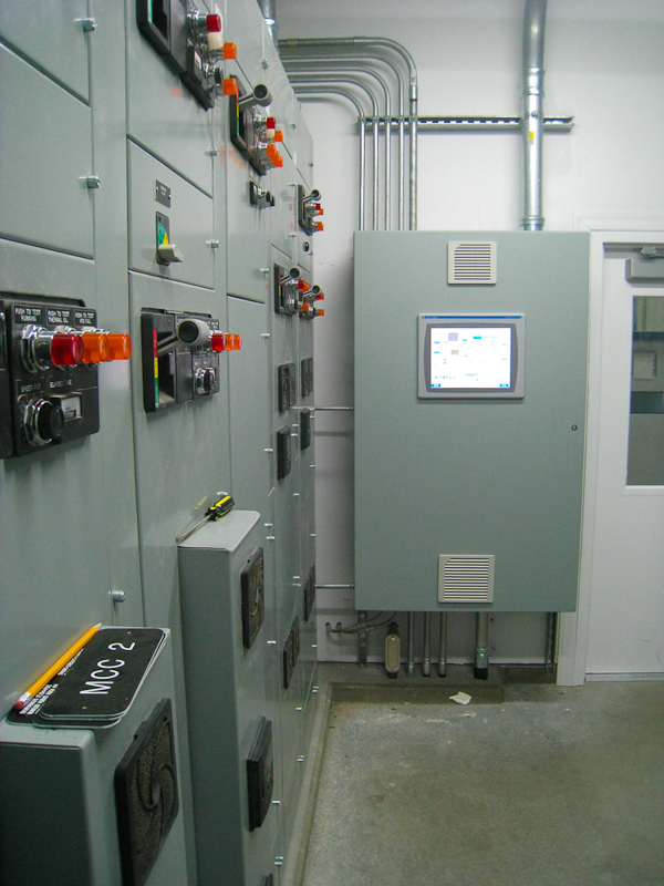
NEW CONTROL ROOM
Picture illustrated the design of the new control and MCC room in the mechanical building. MCC1 (right), MCC2 (left) with the PLC enclosure and operator Human Machine Interface (HMI) touch screen control panel. The ATS is on the back wall (behind the camera).
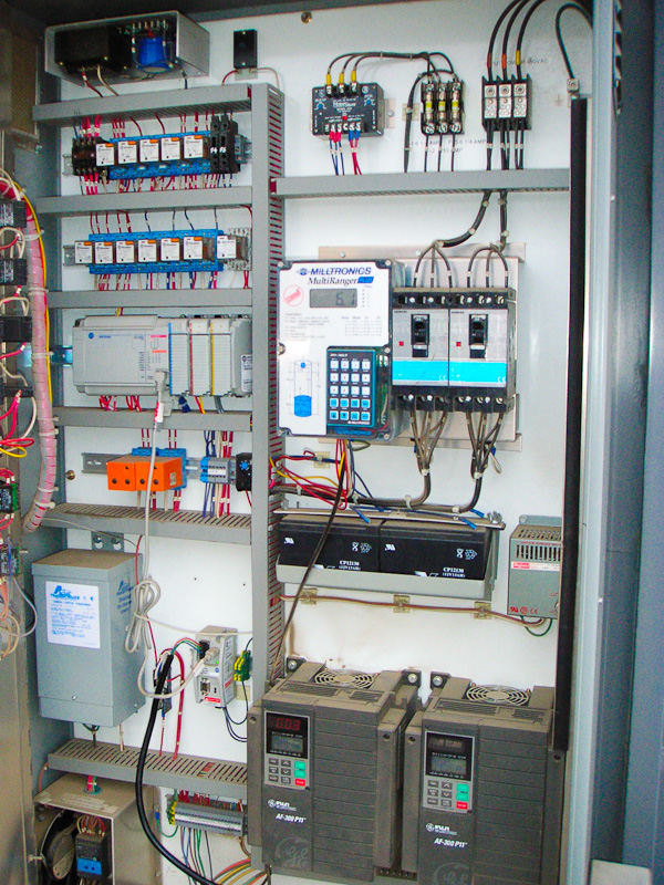
These MCCs were specified as part of the design to house motor starters and other motor controls such as Variable Frequency Drives (VFD).
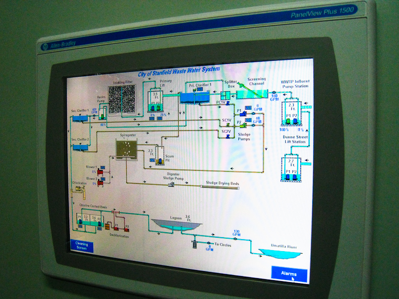
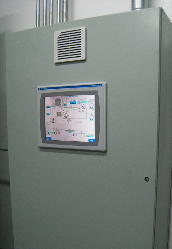
Operator touch screen; centrally located and focal point of system control.
Visible on the fifteen inch display screen at the moment is the main (home) screen depicting an over view of system operation in real time. The system is represented in the diagram using colors to signify status of operating and nonoperation components. Touch a component and its sub screen appears providing more detailed information and settings.

IMPROVED SLUDGE HANDLING
Two new sludge pumps inside the mechanical building. The design included provisions to install a third to be installed when needed. These double diaphragm pumps move sludge from the clarifiers into the spiragester for treatment. Their pump motors are controlled by Variable Frequency Drives (VFD) in the MCC so the flow rate can be automatically adjusted by the PLC to the conditions.
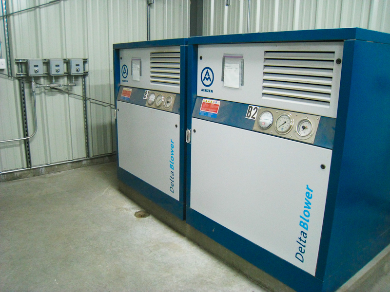
New blowers inside the mechanical building were added to supply air to the spiragester. These 40 HP units are also operated by VFD for improved control and process efficiency.
THE PROBLEM BECAME AN OPPORTUNITY TO OVERCOME THE DIFFICULTY.