Project Description
New Waste Water Treatment Facility
In 2007 the City of Nyssa, OR was nursing along a 50 year old mechanical wastewater treatment plant that no longer met DEQ requirements. For the operators, it was a day to day struggle to keep the plant functioning.
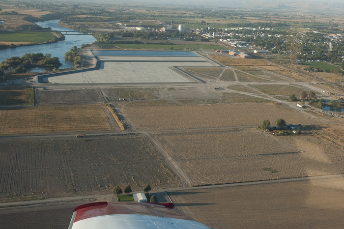
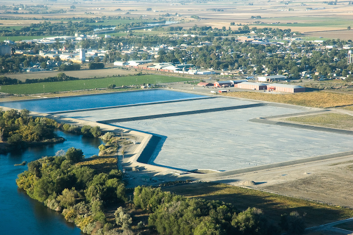
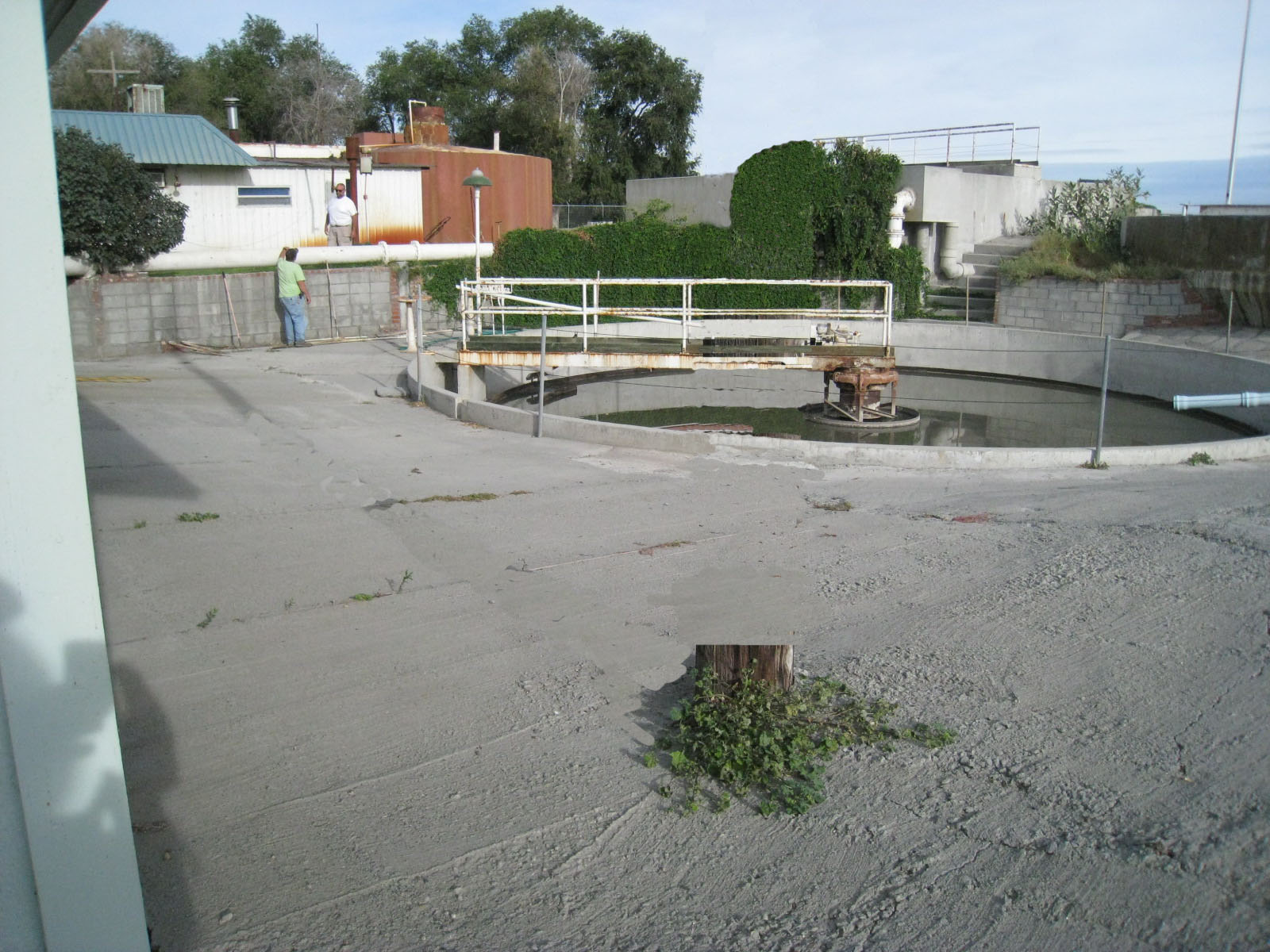
Nyssa’s new approach to waste water treatment pictured above. Included are three lagoons – two for primary and secondary treatment together with a larger water storage lagoon designed to supply irrigation water to over 100 acres of adjacent farm ground. The resulting scope of work for the project was over $6 MM.
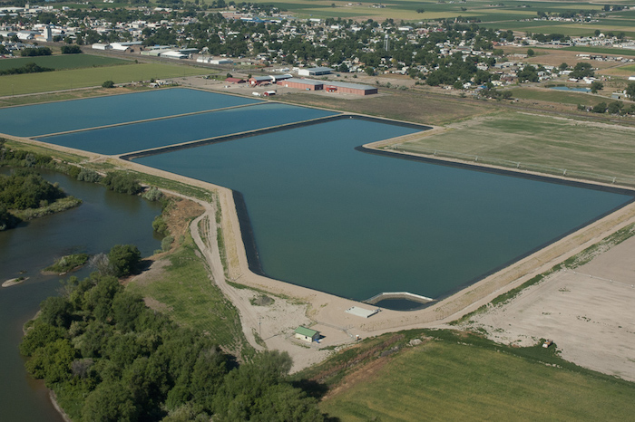
The picture above was taken June 29, 2010 after the lagoons were filled. Treated water moves from the larger Storage Lagoon to the white concrete chlorination structure visible on the bank just above the Irrigation Pump Station. Two of the three new irrigated fields are seen just above and to the right of the Storage Lagoon.
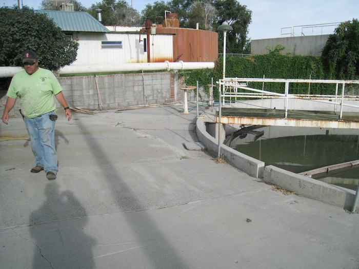


OUT WITH THE OLD
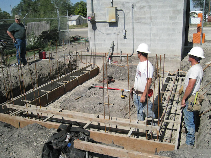
The new simplified lagoon design meant the end for the old mechanical plant digester and skimmer. These were demolished to make way for a new city Operations Building and new Primary Lift Station which screens the water and moves it to the Primary Lagoon.
The new design reuses the water for irrigation instead of discharging it into the river. The farm ground which was available just North of the existing plant no doubt steered the design in the direction of a lagoon solution together with the benefit of water reuse for irrigation of farm ground.a
 a
a
WASTEWATER PUMPS, CONTROL PANELS & POWER OUTAGES
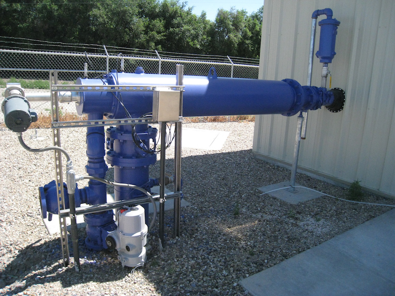
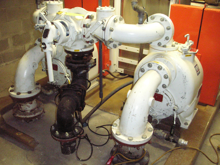
The underground collection system consists of the two outlying lift stations and the Central Station which transfers water to the treatment plant. Several years prior the existing stations were upgraded to suction pumps shown in the picture (left). Unlike submersible pumps these above ground, belt driven pumps can be serviced in place and the operators had found them to be reliable, efficient and easily maintained. Existing pumps at the three stations were retained and the same pumps were included in the new design for the Primary Lift Station.
The Electrical and Control System Design focused early on the key goal of providing the operators with better information as to lift station performance both on site and remotely. Another early concern was for continued operation of the wastewater system during a power outage. It was clear the existing lift station pump control panels with their limited ability that included a red alarm light and a phone dialer were not going to be up to the task. Keeping the three stations operating in a power outage with a single backup generator wasn’t going to be a good solution either.a
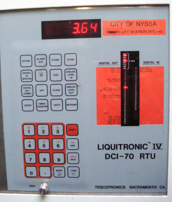
A MORE ROBUST PUMP CONTROL PANEL
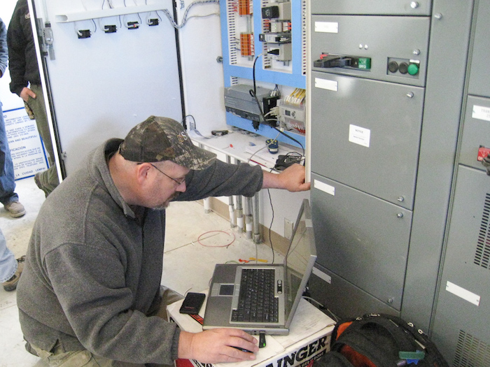
The control system design focused on finding a more robust controller capable of providing individual station performance information to the operators with a remote radio telemetery interface to a central computer capable of recording performance history (SCADA).
The new controller chosen has the ability to monitor the station as well as calculate station flow and volume based on wet well level measurement. All four lift stations were standardized on this controller and interconnected via telemetry to SCADA at the new 1800 Sq Ft operations and shop building constructed at the former mechanical plant site. The design for the new 600 Sq Ft Main Lift Station constructed at the plant site specified these same pumps and controllers.
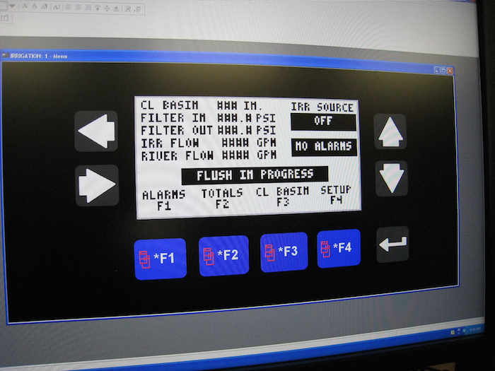
IRRIGATION PUMP STATION ELECTRICAL & CONTROL SYSTEM DESIGN
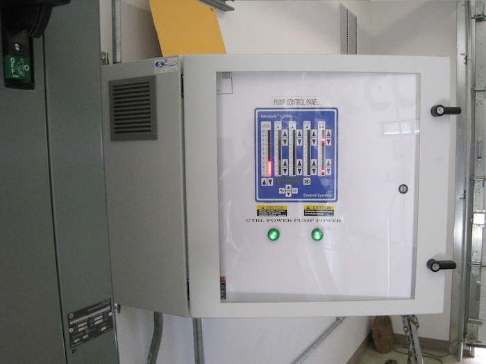
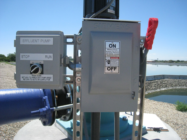
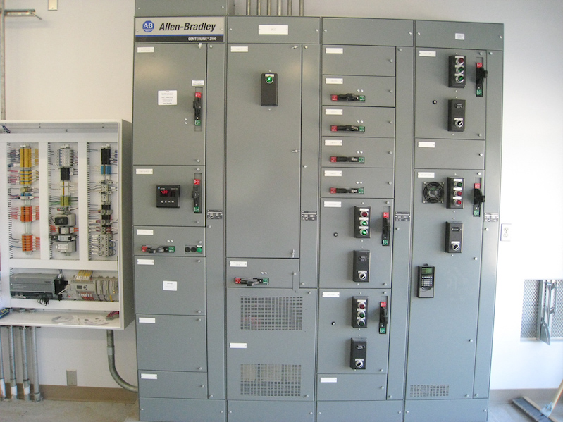
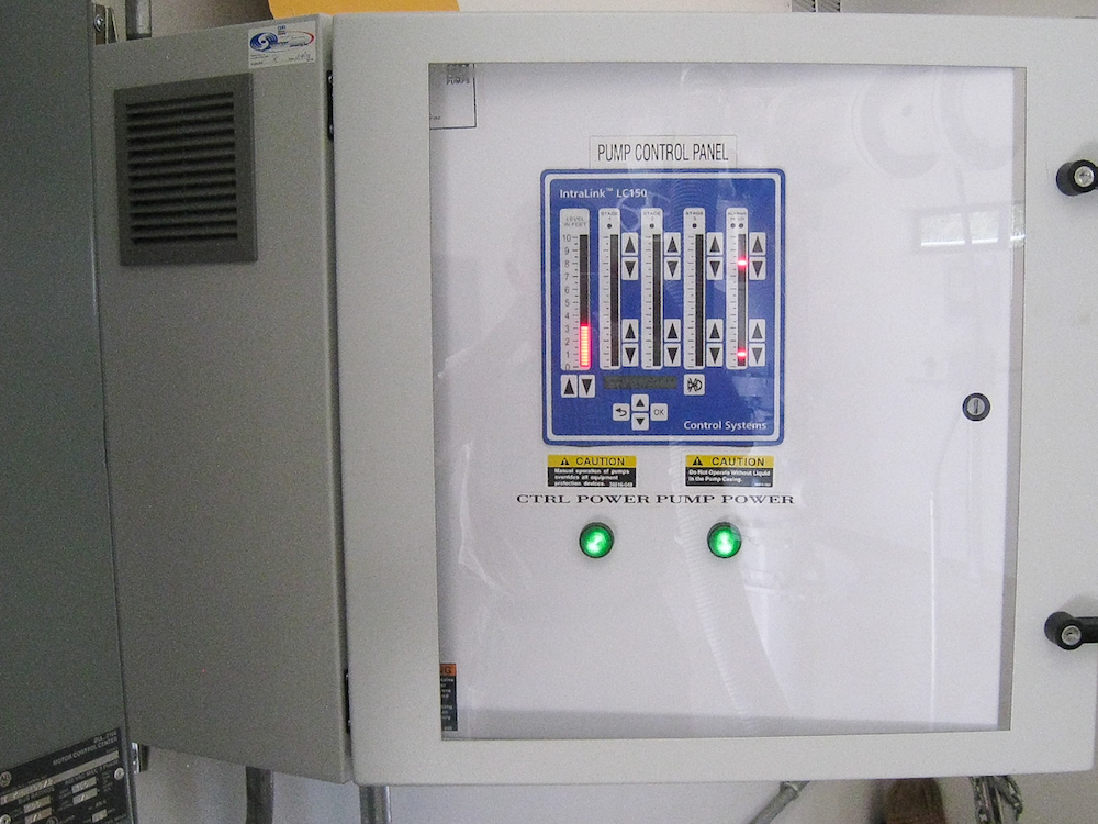
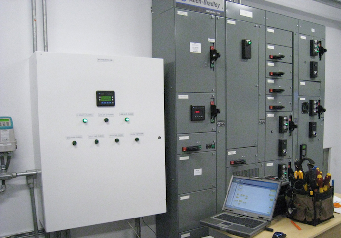
One of the challenges of the control system design was to come up with a simple to operate, cost effective, automatic system to control irrigation water. The resulting design is the white panel (Left) containing a Irrigation System Programmable Logic Controller (PLC). The operator may select any of the 4 linear irrigation machines after which the PLC controls the operation from start to finish.
This includes control of the Variable Frequency Drives (VFD) in the adjacent Motor Control Center (MCC), control of the 5 HP lift pump transferring water from the Storage Lagoon to the Chlorination Basin, water balance in the Chlorination Basin, monitoring and controlling two line pressure pumps supplying the Linear Irrigation Machines as well as their movement. Meanwhile the process can be monitored locally and remotely via SCADA.
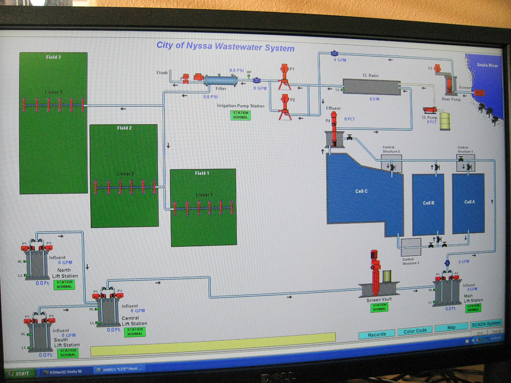
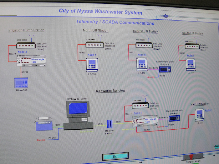
System Control And Data Acquisition (SCADA)
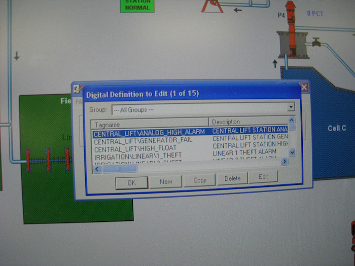
In previous times, operators would typically drive a route to check each lift station. With the new system, data from the stations such as water level, flow and status is automatically updated and displayed in real time. Operating parameters such as data, events and alarms are logged and stored by the SCADA Computer to provide operational history which is valuable for regulatory reporting, routine maintenance and troubleshooting.
Look closely at the operator screen (Left) to identify system components which are represented graphically and arranged to mimic the layout of the actual system. Colors indicate component status; key operating data such as flows are indicated numerically and a component requiring attention or intervention will alert the operator on the screen or via phone message.

WASTEWATER NOW REUSED FOR IRRIGATION
Most people think of circular “pivots” when it comes to overhead sprinkler irrigation. This was the initial thought here as well but as you can see on sheet E1 above, the property is rectangular which would have required up to six circles to cover the area. Only one linear machine for each of the three fields was required and coverage turned out to be more uniform without gaps or overlap.
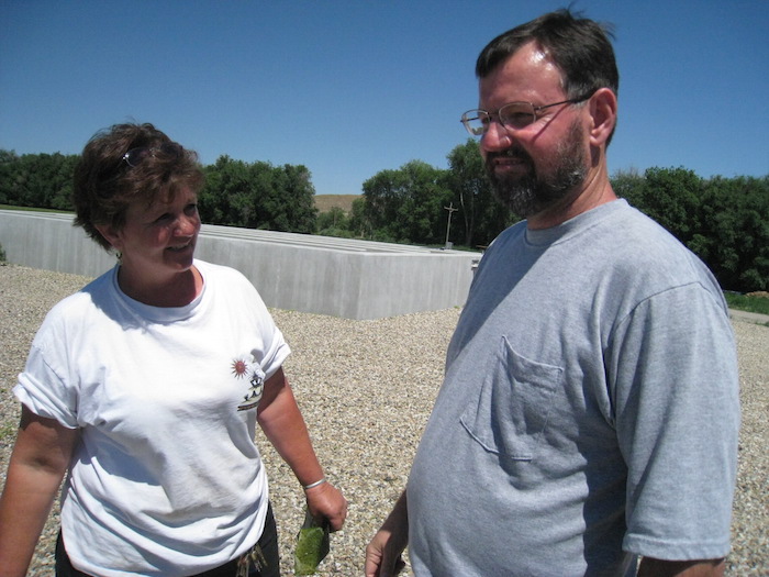
At the completion of the project in 2010 the Public Works Water Supervisor for the City of Nyssa had the following statement regarding the project:
A
A
“On a scale of 1 to 10, we got an 11”