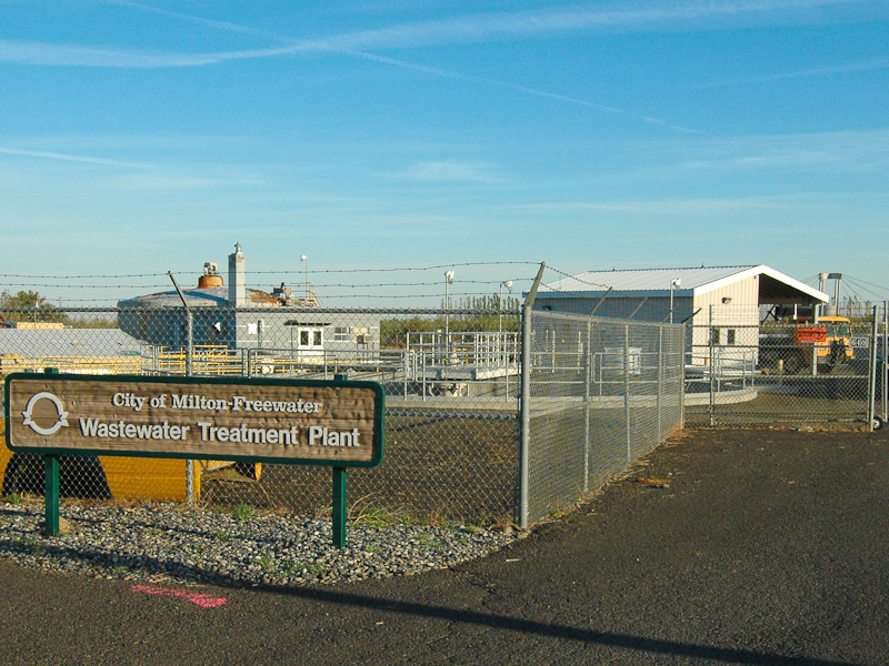
Project Description
Project Electrical Engineer: Wastewater Treatment Plant
Completed 2016: Milton-Freewater, OR
- Treatment plant Electrical redesign: leveraged existing components; supported new process improvement.
- New Process Automation & Monitoring System: Plant Wide. Design included Graphic Operator Control Panels.
- Water treatment Improvements included Influent Screen, Primary & Secondary Clarifiers, Trickling Filter, more.
- Sludge Processing included: new Automated Digesters, Sludge removal system, Waste Gas Flare.


 AUTOMATION OF WASTEWATER TREATMENT PLANT
Design objective was to provide automated process control with information the plant operator can use to control and optimize the treatment process.
Design included a central Programmable Logic Controller (PLC) located in the Operations Building communicating over an Ethernet/IP network with remote instrumentation and control input/output racks.
This architecture supported a distributed network interface to Motor Control Center (MCC) for motor starters and Variable Frequency Drives (VFD) in addition to inputs such as flow rate or level and outputs used to initiate control actions or sequences.
OPERATOR CONTROL & MONITORING: THE HUMAN MACHINE INTERFACE (HMI)
Automation System interface was designed around an interactive color touch screen (i.e. smart phone). Graphics depict system components and their status. The result is a picture of the treatment process state in real time.
Touch a component on the screen to bring up available information, settings or view history. The design includes panels at two locations within the site for both operator convenience and for redundancy.
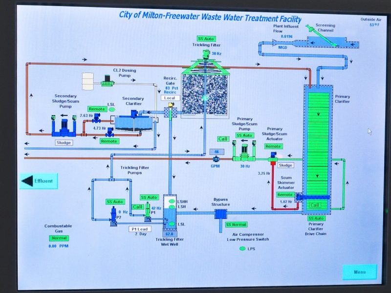
HMI CONTROL & MONITORING: SCREEN 1
Click on the image to view larger.
Influent (raw water) enterers the plant at the Screen Channel where trash is removed (picture upper right) then flows to the Primary Clarifier where scum and sludge are removed. Follow the water path to the Trickling Filter Distributor then to the Secondary Clarifier for second scum and sludge removal.
Colors indicate status of pumps – Green for running, Red or Blue for off. Water lines are Blue; waste lines are brown.
Plant components visible in the areal picture at the top of the page also appear on the screen with their status indicated.
This graphic picture is an overview. Control and monitoring of individual components as well as the process occurs by the plant operator interacting with the screen.
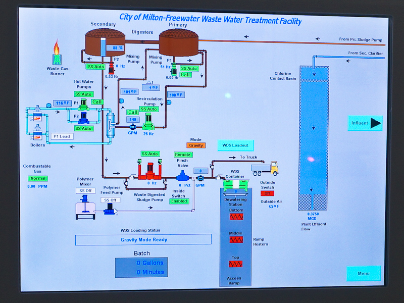
HMI CONTROL & MONITORING: SCREEN 2
Click on the image to view larger.
Digester process and effluent including water and sludge removal from the plant appear on this second screen.
Water is chlorinated after which it is clean enough to be discharged (picture right). Sludge and scum are pumped to the Primary Digester then flows to the Secondary Digester. Digested sludge rich in plant nutrients is trucked from the plant to be land applied. (see below)
Methane gas, a byproduct of the digester, is burned off on site by the gas flare. Gas production by the plant is sporadic and insufficient for economic beneficial use.
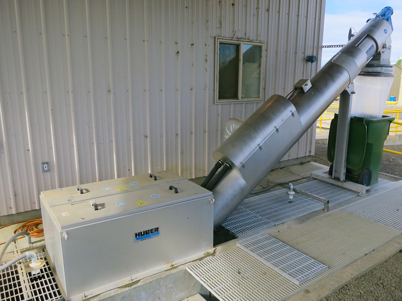 TRASH REMOVAL: SCREENING CHANNEL
It removes inorganic materials from the water such as grit, sand or trash while passing liquids and organic solid matter. Water flows on to the Primary Clarifier under the grate while trash removed from the water collects in the green bin.
Raw wastewater enters the plant under the grate on the left side of the picture where a level detector signals the mechanical screen to start.
The existing screen unit was replaced with this upgraded unit and controls relocated inside to be closer for the plant operator. Screen operation is automatic with monitoring by the plant wide automation system.
The Screening Channel location is on the North side of the Headworks Building and not visible in the aerial picture top of page but you can see the water path emerging from the building to the Primary Clarifier.
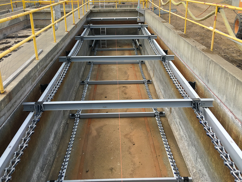 SLUDGE & SCUM REMOVAL: PRIMARY CLARIFIER
Operates on an automated, repetitive sequence process in this rectangular pool. This is the first raw water treatment that simultaneously removes solids which settle (sludge) and lighter oils and soaps that float (scum).
Controlled by the PLC Automation System, chain flights at the bottom push sludge to a collection pit at the close end while the flights on the surface push floating scum to the far end where an automated quarter turn skimmer captures and removes it to a collection pit.
While collection is taking place a pump removes the sludge and scum transferring it to the digester in two separate automatic operations. This cycle repeats automatically on a schedule set on the HMI by the plant operator.
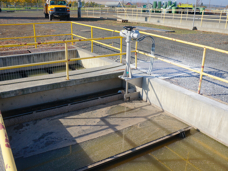 NEW SCUM REMOVAL SKIMMER
Operates automatically together with the upper flights. As floating debris is pushed toward the notched trough it rotates a quarter turn down collecting scum then back up to drain it to the new scum pit visible to the right of the actuator.
A complete cycle (sludge and scum) has several moving parts controlled automatically by the PLC. First the chain drive starts moving the flights to collect sludge and scum. Scum skimmer actuations follow filling the scum pit. Sludge is collected at the same time in a submerged pit at the other end.
While collection is in process a positive displacement pump in the basement of the Operations Building cycles between sludge and scum with the use of a 3-way valve moving the material directly to the digester.
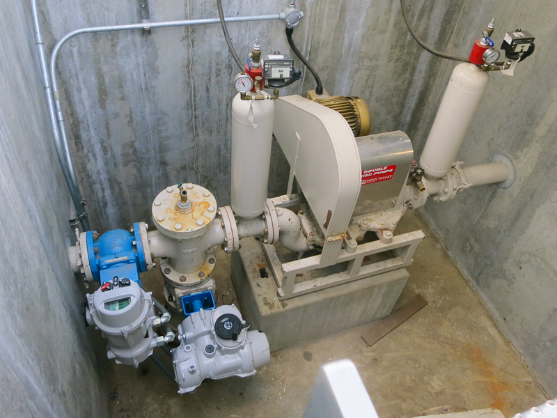
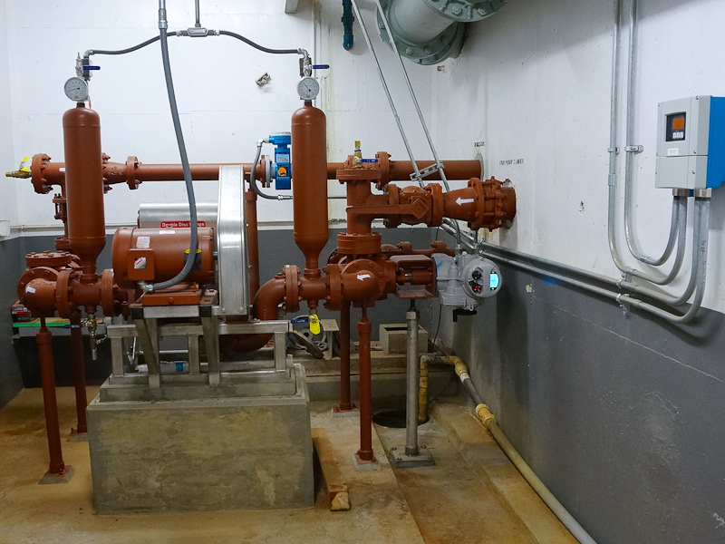 NEW SLUDGE/SCUM PUMP
Solid matter and scum removed from the water is transferred separately to the digester by this variable speed, positive displacement pump.
A motorized quarter turn valve actuator (picture right) is first positioned for sludge by the PLC followed by pump start at the MCC. While pumping a magnetic flow meter (picture center) monitors the flow rate and records the quantity. After sludge is transferred the actuator is repositioned for scum followed by a similar operation.
Process automation such as this can improves efficiency and increases project value. It is but one example of the collaborative Electrical Design process.
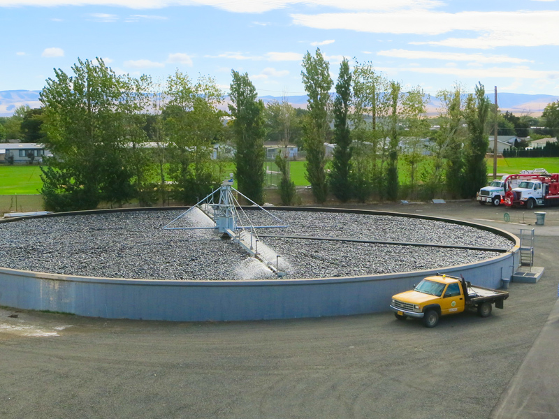
 TRICKLING FILTER
Water from the Primary Clarifier is sprayed over the rock bed by the revolving distribution arms of the trickling filter drive. This process is designed to aerate the water while the bio-film growth of microorganisms on the rocks similar to algae removes dissolved solids from the water.
The rock bed must be kept wet to grow microorganisms. Settings on the system HMI permit the operator to do this by a combination of varying the rotation speed of the arms with a new variable speed drive motor and by setting the water flow rate using the new variable speed pumps.
Automation of this process is more involved because it requires water management from two sources – see next.
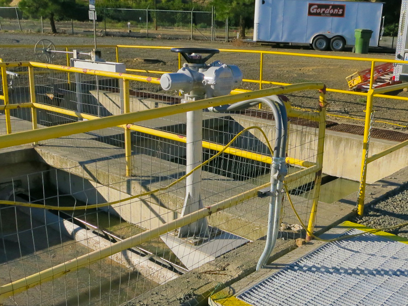
 ACHIEVING CONSTANT FLOW – RECIRCULATION
With a peak plant capacity of over a million gallons per day, flow rates vary significantly over time and will not support a constant flow to the Trickling Filter.
The plant had this existing recirculation pit with manually adjustable slide gates to address this but without continuous adjustment it was either too much or too little recirculation.
The Electrical Design addressed this with the addition of a motorized slide gate actuator to vary the flow rate of water being recirculated to the trickling filter.
The result is another example of how the new plant automation has improved efficiency and relieved the operator of the mundane tasks allowing him to focus on the bigger picture of process optimization.
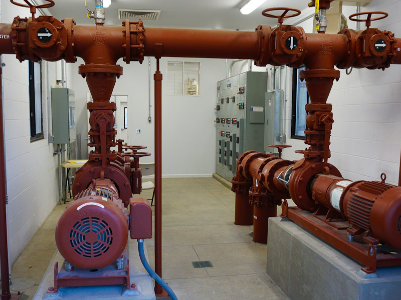
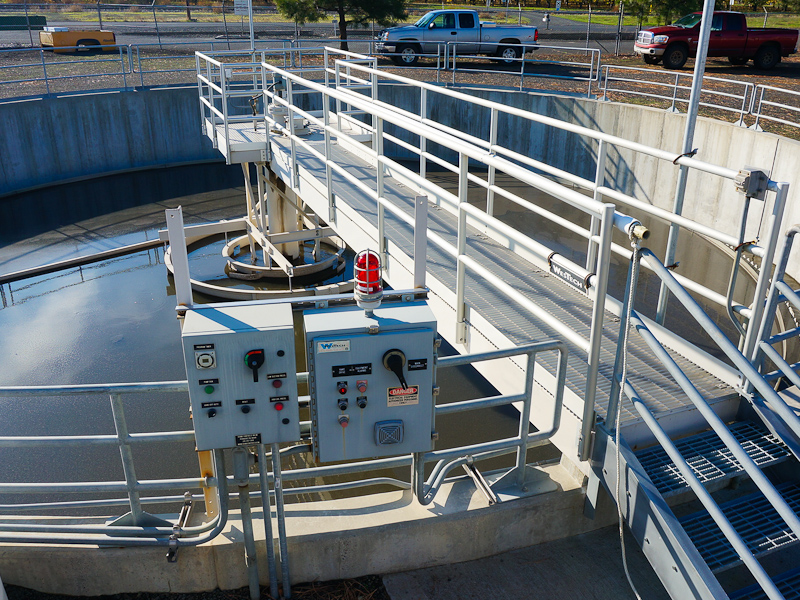 SECONDARY CLARIFIER
Water from the Trickling Filter flows here for a second round of sludge and scum removal before the water is discharged from the plant. Separating sludge and scum from wastewater is the simple but relatively involved “mechanical“ part of the overall treatment process.
Like the Primary Clarifier sludge settles and a slower rake arm skims remaining scum off the surface. A second pump moves the sludge and scum from collection pits so that it ends up in the digester. The removal and pumping process sequences are setup on the HMI by the plant operator to be controlled by the automation system.
Existing clarifier and pump control panels (picture) were reused after modifications enabling control and monitoring by the plant wide automation system.
From here water flows to the Chlorination Basin alongside the Primary Clarifier where remaining bacteria are killed. This completes water processing. It’s now clean enough to discharge from the plant and find its way back into the ground.
Sludge is another matter.
AUTOMATED CONTROL OF ANAEROBIC DIGESTERS & SLUDGE DISPOSAL
- Sludge and scum removed from the raw water remain in the plant for additional processing in the Primary and Secondary Digesters.
- ANAEROBIC DIGESTION is a biological process in which microorganisms break down sludge and scum in an enclosed digester tank.
- Over a period of days bacteria break down (digest) the material, reduce its volume, odors, and rid it of harmful organisms.
- The end result is a fertilizer material containing plant nutrients that is loaded into a container in the Dewatering Building at the bottom of ramp (picture) and trucked from the plant to be land applied.
- A byproduct of digestion is methane gas (aka biogas) which is burned on site by the gas flare.
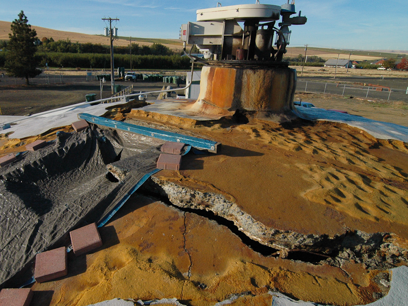
 PRIMARY DIGESTER
The Plant Wide Automation System maintains efficiency of the bacteria growth (bugs) that do the work of breaking down sludge.
The process is enhanced by constant agitation of a variable speed 5 HP vertical recirculation pump (picture). Temperature of the process is maintained by a pair of redundant 45 KW hot water boilers and heat exchanger providing optimal conditions for bacteria growth.
A control loop maintains the digester tank contents at 110 ºF while additional mixing can be provided on an operator set schedule by a 15 HP variable speed mixing pump.
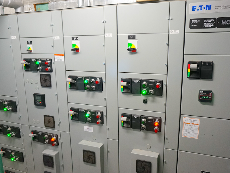
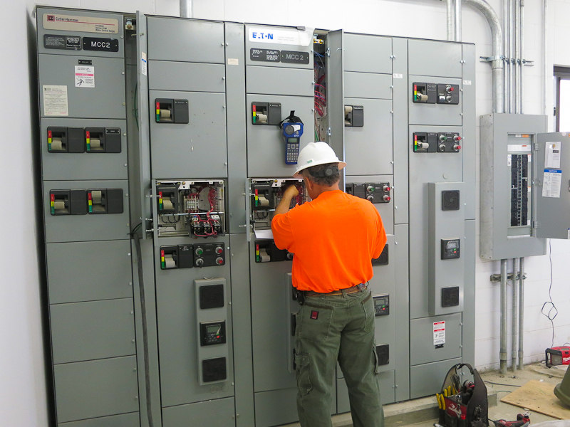
 MOTOR CONTROL CENTER (MCC)
A well-designed and integrated MCC brings a number of benefits to the project including value. Typically it will house the control components for motors that do the work in the Digester Building such as starters, overloads and Variable Frequency Drives (VFD).
The MCC monitors incoming power quality to ensure reliability of three phase motors. Control components are selected and specified for their ability monitor individual motor parameters enhancing efficacy and reliability.
The plant typically runs in AUTO mode under control of the PLC automation system or the plant operator can intervene from the HMI. The MCC provides full manual control of each motor at the front panel when necessary.
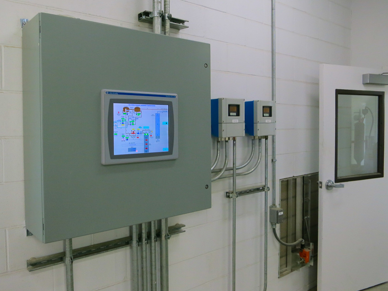
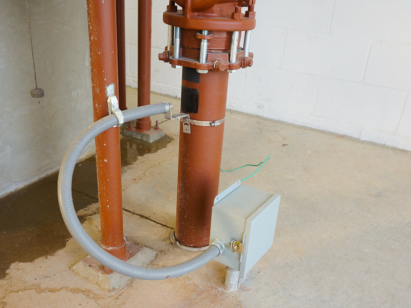 DIGESTER THERMAL CONTROL
Temperature control in the Primary Digester was designed around continuous recirculation of the closed tank contents together with a heat exchanger with a hot water loop provided by the boilers discussed above.
To maintain the operator set digester temperature automatically the control system monitors the following three parameters: hot water temperature, sludge temperature to digester and sludge temperature from digester.
The design evaluated a number of methods to accurately measure these temperatures but none were as simple, reliable and precise as the noncontact inferred thermometer shown in the picture on the sludge return pipe.
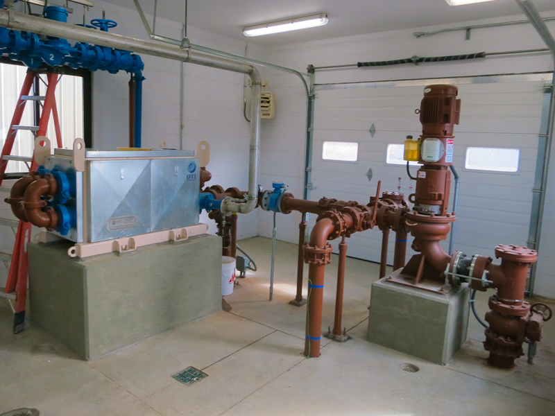
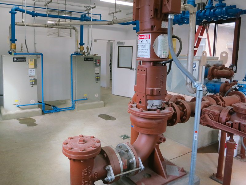
 MIXING PUMPS
At times additional agitation is required in the Primary and Secondary Digesters which is provided by these two 15 HP variable speed pumps.
The plant operator can call either to run manually from the HMI or directly from the controls at the MCC. More typically they operate on an automated schedule of frequency and duration set by the operator.
The picture inside the Digester Building shows the layout of the control enclosure and HMI (left), the MCC on the opposite wall and the mixer pumps in the foreground. The other control enclosure with the second HMI is located in the Operations Building.
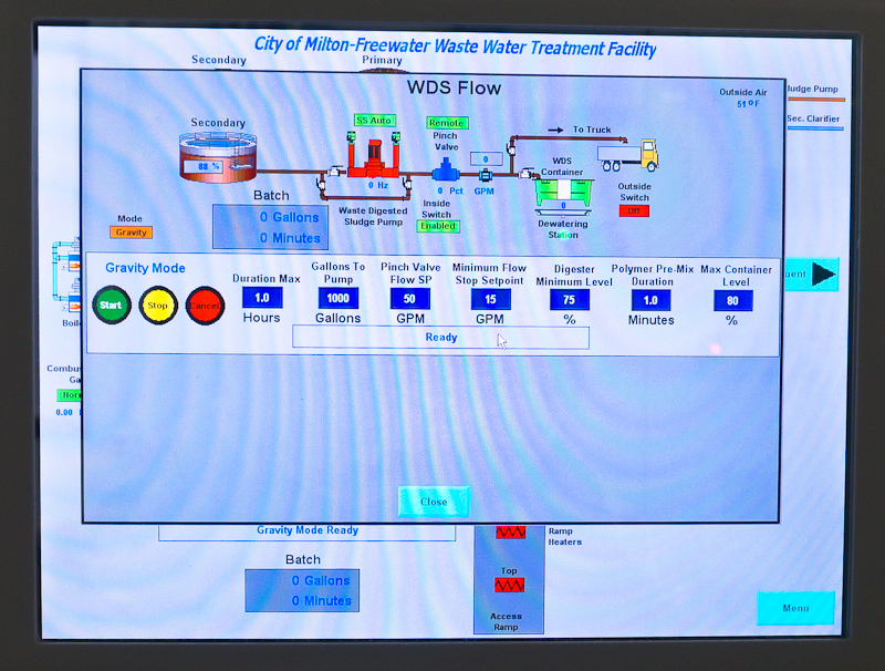
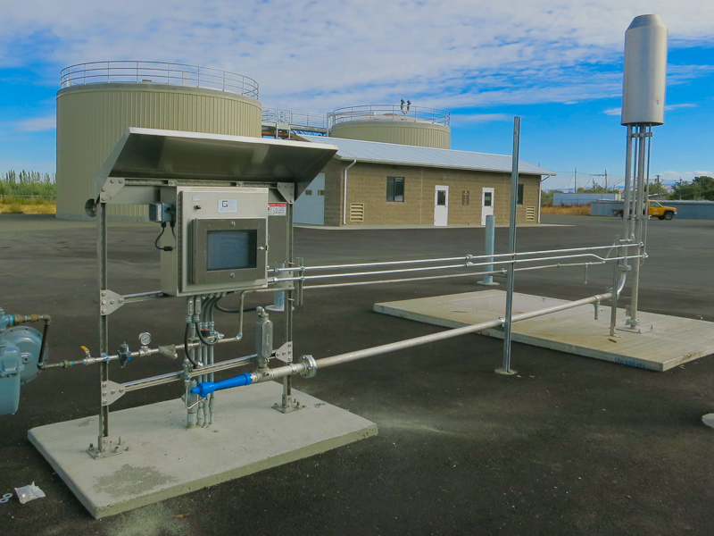
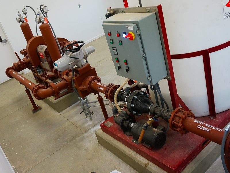 SLUDGE HANDELING & LOADING
One of the early design objectives was to improve sludge handling and removal at the plant. Contents when removed from the Secondary Digester are digested sludge in a water suspension requiring the sludge to be dewatered prior to removal from the plant. To aid “dewatering” of the sludge a polymer is added to the mix as it is removed from the digester.
The sludge/water mixture can flow from the digester by gravity or be pumped to a pinch valve having an actuator to automatically control flow rate (see picture). Polymer is premixed in the white tank, injected and mixed with the sludge/water.
From the Digester Building the sludge flows to the Dewatering Building and into a removable container – see below. Alternately it can be loaded at the outside loading station.
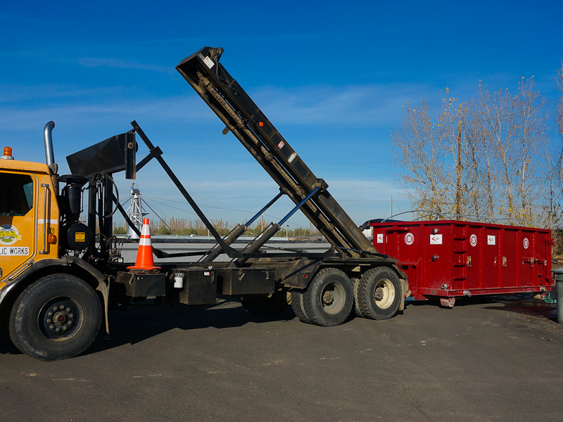
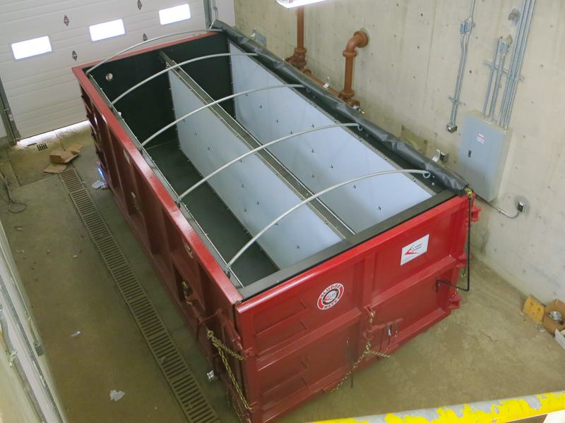 SLUDGE DEWATERING & TRANSFER CONTAINER
With polymer added the sludge/water mixture flows the Dewatering Building and into each side of this container. The white panels are perforated; designed to let the water pass and drain out the bottom while retaining the sludge. Water then flows to the floor drain.
The plant operator sets up and initiates the sludge removal process on the HMI. Options include filling the container or a truck directly; dispensing a preset gallon volume or the container can be filled automatically to a preset level.
When filled and after dewatering is complete the container is loaded on a roll-off truck and removed up the ramp. Once in the field land application occurs by opening the container end gate and raising the front discharging the contents.
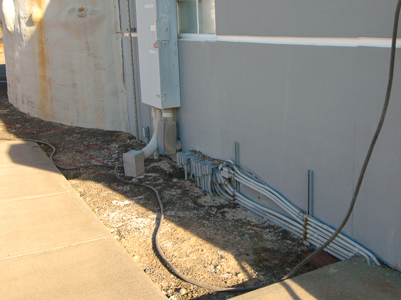
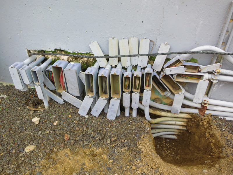
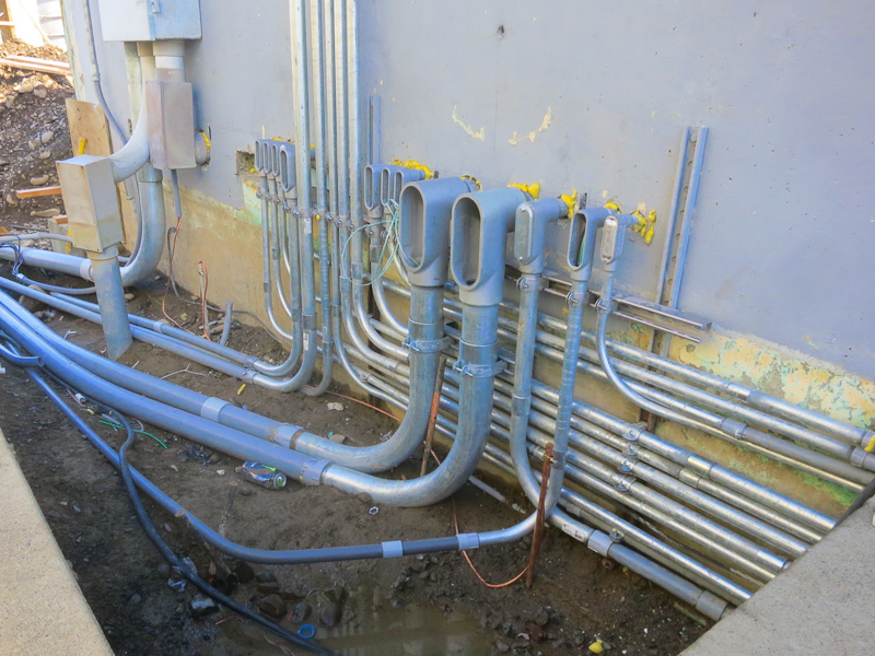
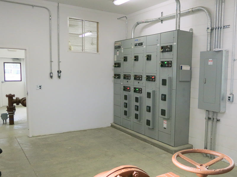
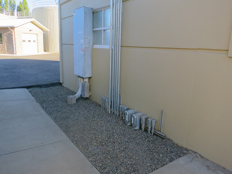 ELECTRICAL DESIGN: Circuit by circuit. . .
…and conduit by conduit the existing treatment plant electrical system and process was documented as a first step in the new Electrical Design. Existing components were evaluated for possible reuse in the new design; or perhaps for replacement or upgrade or future usefulness. Those with no further value were removed.
But existing components that were reused saved money like the existing service dis¬connect (picture). Existing conduits were rewired. Existing influent and effluent instrumentation was reused. The existing standby generator was rehabilitated and reused; just to name a few.
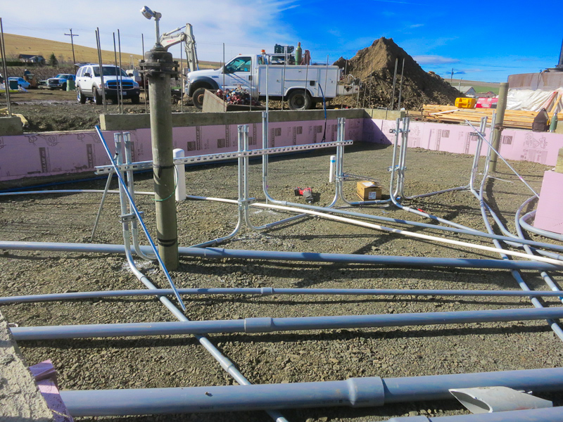
Industrial grade electrical components were specified and used throughout including rigid conduit and cast metal boxes. This “after” picture illustrates conduits installed as specified in the Design Drawings: “. . shall be run parallel to building lines and tight to the wall surface . . “. Find the “before” picture in the Gallery above.
CALL TO DISCUSS YOUR NEXT PROJECT.