Project Description
Wastewater now reused for irrigation. And the cities of Burns and Hines have a new source of revenue from rented farm ground. The Electrical and Control System Design included:
- Three Pivot Irrigation Machines providing a total of over 160 Acres of farm ground
- A new Burns Pumping Station to supply pivots and transfer water to storage lagoon
- A new Hines Pumping Station for transfer of treated wastewater to storage lagoon
- A new Automated PLC Control System and Operator Interface at Burns Pumping Station
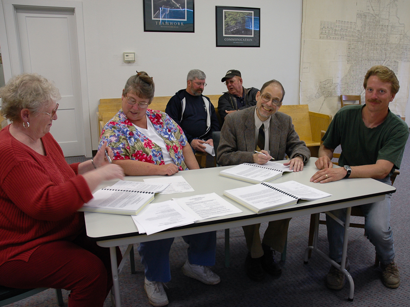
This project got underway with a conference at the Civil Engineers office in Mt Vernon, OR after the original civil engineer had unexpectedly passed away. A team of three Engineers would see this $2,500,000 project to completion – two civil engineers and the Project Electrical Engineer.
The scope of the project was expansive covering hundreds of acres and involving a joint venture between the two adjacent cities in central Oregon; Burns and Hines.
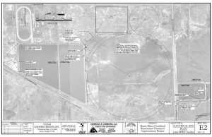
Hard to imagine but Sheet E2 of the 11 Sheet Electrical and Controls Drawings for the project represents over 500 acres. Burns primary and secondary lagoon are center left while the smaller Hines lagoon is going off the right edge just below center.
One of the driving needs was water reuse which was accomplished using the 3 pivots; the large one center right and two smaller ones – left and top right. To make this work, a joint storage lagoon was required; top center.
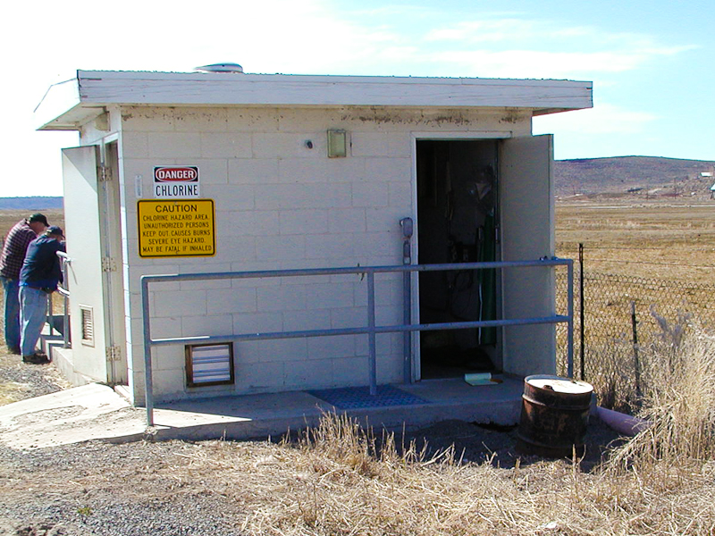
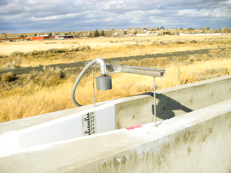
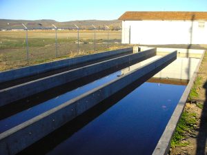 Burns chlorination basin and new pump house. Originally both cities had essentially the same setup – primary and secondary lagoons, chlorination and discharge. A wet well and pump house was added at each site. Pivot pressure pumps were located at the Burns pump station but the design included the ability of both stations to pump to the joint storage lagoon. Elevations were designed so that water would gravity flow from the storage lagoon to the Burns station for subsequent transfer to the pivots.
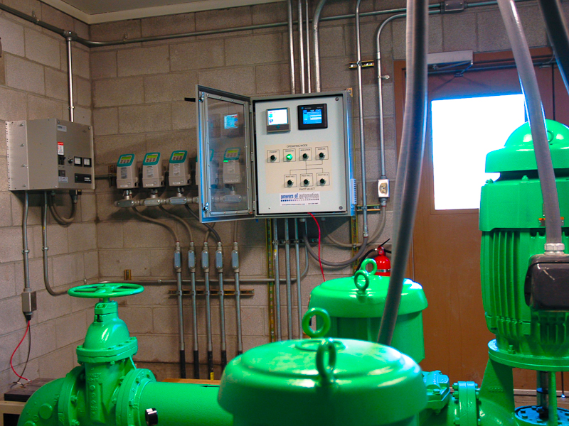
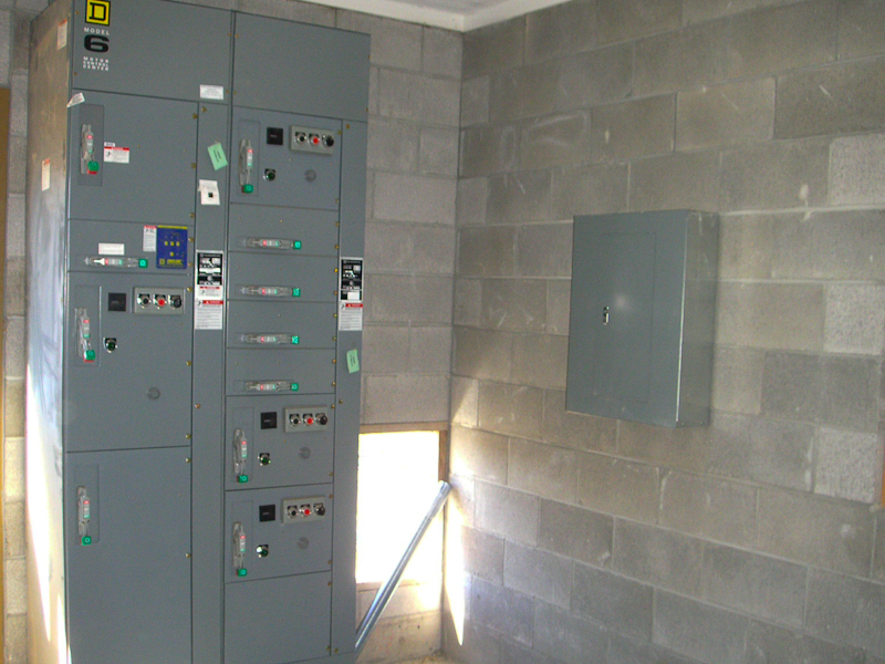
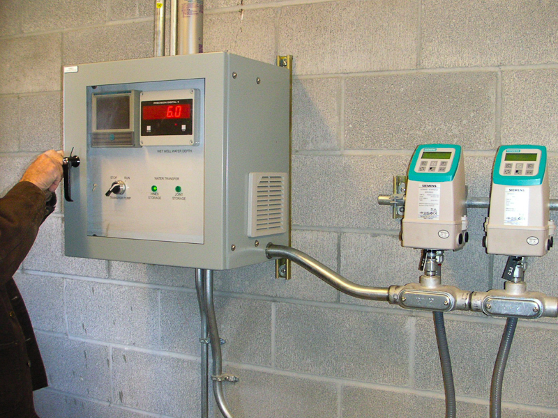
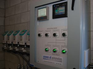
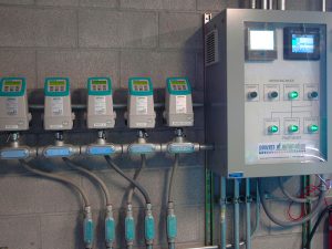 Main PLC Control System and Magnetic Flow meters at Burns Pump Station. One of the Design challenges was to balance the flow in and out of the wet well from two sources coming in and three going out to the pivots. A closed (PID) control loop was used with inputs from a level sensor and magnetic flow meters while the PLC controlled the electrically actuated plug valves to control water flow into the wet well.
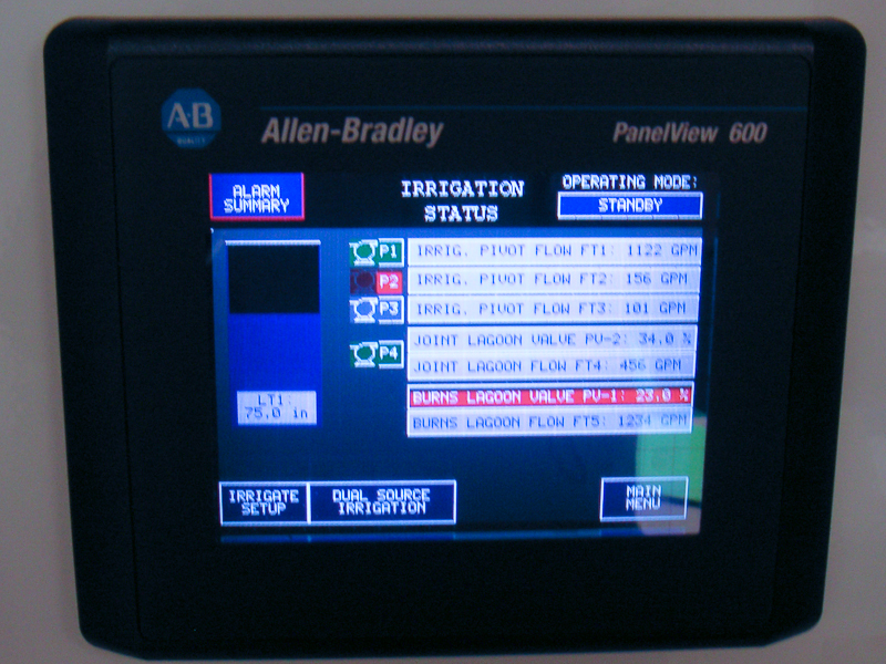
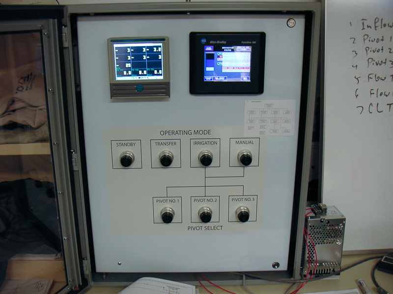
Operator simplicity is illustrated here – 7 lighted pushbuttons. Transfer pumps to the storage lagoon. Irrigation pumps to selected pivots (1-3). The operator selects one or two sources from the touch screen upper right. Manual provides full control via the touch screen.
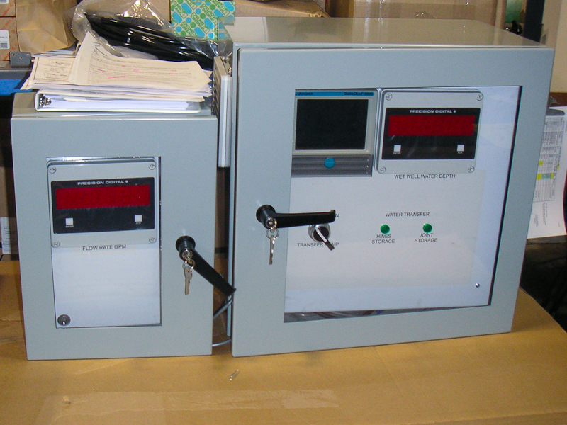
Neither city had much of an appetite for a full Supervisory Control and Data Actuation (SCADA) system but yet there was still a needed to record water movement. To address this in an operator friendly manner a paperless chart recorder was specified at each station. It is visible through the upper left of the glass in this and the previous picture.
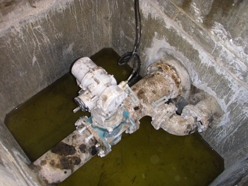
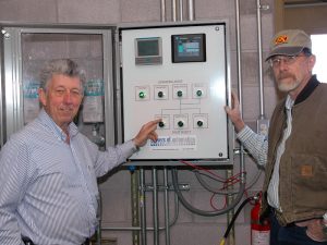
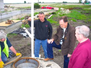 Doug Ferguson, PE and Pat Curran, PE the two Civil Engineers inspecting one of the valve and flow meter vaults. Rising ground water in the spring of the year created difficulty with the vaults flooding until the contractor got them sealed. Both the electric actuators and the magnetic flow meters had been specified waterproof (IP67) so this was more of a nuisance than anything else. One of the actuators can be seen in the Gallery above after it was submerged for the winter months. It was cleaned up and worked just fine.
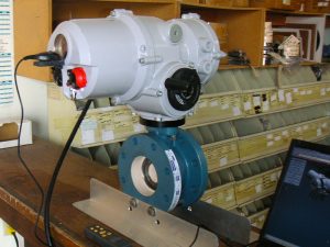 Actuator specified for use on the project together with one of the valves. These devices provided control of gravity flow water.
Electric actuators can be a problem if utility power is lost. The control system design included a 24 V DC backup power source to provide power for the actuators, PLC and instrumentation. On loss of utility AC power the system shuts down automatically and continues operation when power resumes.
